Welcome to Just Commodores, a site specifically designed for all people who share the same passion as yourself.

New Posts Contact us

Just Commodores Forum Community

It takes just a moment to join our fantastic community

Register

Engine/ECU swap - now fuel pump not working

alexp36

Keep honkin-I'm reloading
Joined
Jan 3, 2007
Messages
74
Reaction score
1
Points
0
Members Ride
VR Executive
Ok, I've taken a 5L and computer out of a VN, and put them into my VR.

I know this is probably a bit dodgy, using the VN ECU, but I don't have the cash to buy another ECU right now.

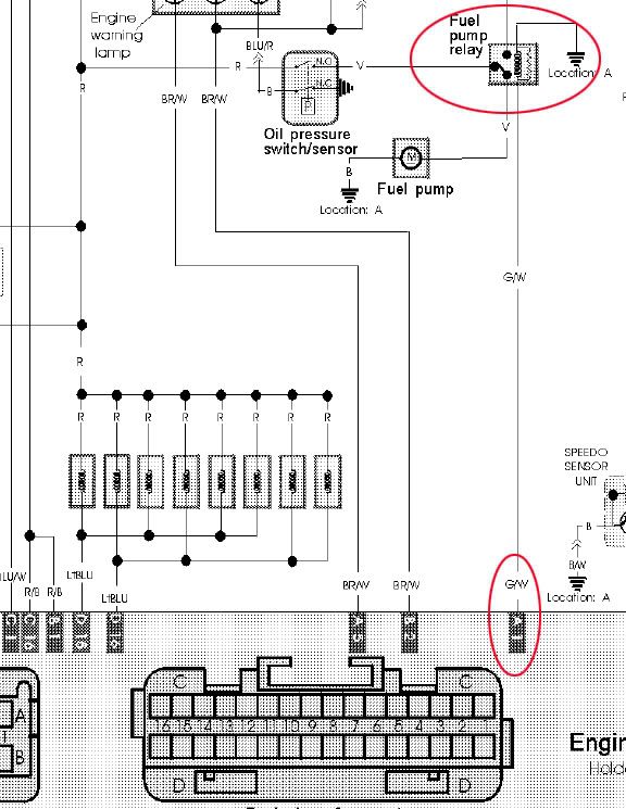
So far it will start up and run fine, but only if we bypass the fuel pump relay. Without bypassing the relay, the f/pump won't run at all.

I've looked at wiring diagrams for the two different ECU's, but I don't know enough to understand what I'm looking at.

Does anyone know if this means I need to get a VR computer? Or could it be some simpler problem, like a wire not connected somewhere?
 

IvanTheTerrible

New Member
Joined
Jan 7, 2010
Messages
82
Reaction score
1
Points
0
Members Ride
VH Commodore
Vn and VR computers are different.
 

bhopper

Member
Joined
Dec 19, 2009
Messages
135
Reaction score
2
Points
18
Location
east of melbourne
Members Ride
vt spac supercharged 6,vp bt1 5.0,vyss lshulk
Hi there this is the website for dr bob he has a list of all the memcals that are in commodores.Was your vr originally a 5.0 if so just try and find the pinouts for a vn and vr you might just have to swap a wire or if its running ok just put your own relay in it.he also has wiring diagrams for them aswell on there you should be able to work it out .Also let us know what you have changed and keeped so i can try and help you out need the info .

Rob's Creative Calibrations

hope that helps
 

alexp36

Keep honkin-I'm reloading
Joined
Jan 3, 2007
Messages
74
Reaction score
1
Points
0
Members Ride
VR Executive
Not originally a 5L no. Was a V6 (Executive).


I know nothing about wiring and/or wiring diagrams... but I've downloaded the VR V6, VR V8, and VN V8 diagrams.
Looks to me like the fuel pump relay is activated by pin A1 in all 3 diagrams.

Here's what I'm looking at, example is from the VR V8 diagram:
VRV8_wiring_Fuel.jpg


Am I reading that right? Also, is the little arrowhead shaped symbol (beside the fuel pump on the diagram) an earth?

If I'm reading the diagrams right, it looks like the computer on both VR and VN uses the same pinouts for the fuel pump relay. Which presumably means we have some other wire connected wrong.

What we have changed and kept:

Took out original VR 3.8 V6 and trans and computer and wiring loom for computer.
Put in 5L and VN trans and VN computer and wiring loom going to the computer.

My father-in-law did most of the work, so unfortunately I can't tell you a lot about the wiring, except that we have re-connected everything on the 5L as it was on the VN (both VN and VR were running prior to engine swap)
He is a mechanic, has been doing it all his life, currently works at a good local mechanic shop, and has done plenty of engine swaps and other odd jobs. But he isn't specialised in auto electrical. Presumably if it was his car, in his garage, he could spend the time to nut out this issue, but so far hasn't been able to on mine.

I may end up calling out an auto-electrician to have a look at it. Just didn't want to pay the call out fee if it's only something minor.
 

alexp36

Keep honkin-I'm reloading
Joined
Jan 3, 2007
Messages
74
Reaction score
1
Points
0
Members Ride
VR Executive
Ok, I've now located what I think is the fuel pump relay wire on the ECU connector. It's a green wire, with a white stripe. Which is correct as per the diagram, and in the correct place (a1).
I've traced it through, and it is connected to what I guess is the correct pin on the actual relay under the bonnet.

So far so good. I guess now I need to test if there is power going to the relay when the key is turned on, correct?

I have a tester, but I'm not sure how to do this test. What range should I set it to. Obviously one of the DC settings, but which one?

Then I guess i need to stick one probe in the socket where the green and white wire comes up in the relay, and the other probe in the socket opposite?
Or should I earth the other probe on the body?
Then test with key on and key off.
What should I see? voltage with key on? all zeros with key off?

As you can tell, I know stuff-all about this stuff... but I'm keen to try it if anyone can give me some more help.
 

alexp36

Keep honkin-I'm reloading
Joined
Jan 3, 2007
Messages
74
Reaction score
1
Points
0
Members Ride
VR Executive
Ok, problem fixed.
Was a mismatch between wires/pins on a connecter between the loom from the VN, and the original wiring going to the relays on the VR.

Basically, the green and white wire was in the wrong hole...
Pulled it out of the connector block, and put it back in the right hole, and now it works!

Thanks to those who suggested looking at the wring diagrams. It really helped.

Now I've just got to finish off a few more tasks, and I'll have the car back on the road. Main one is I need a section of exhaust made up, between the single pipe out the back, and the headers, been quoted about $150 at local exhaust shop, so should be able to get that done pretty soon.
 
Top