Welcome to Just Commodores, a site specifically designed for all people who share the same passion as yourself.

New Posts Contact us

Just Commodores Forum Community

It takes just a moment to join our fantastic community

Register

Wiring Help

VSEXEC

Member
Joined
Jun 16, 2005
Messages
156
Reaction score
0
Points
16
Age
38
Members Ride
VS EXECUTIVE
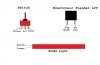
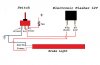
Hey guys having a little trouble with a bit of wiring at the moment. I have a maloo led light from the sailplane and want to wire it to a switch and a flasher can. I have attached a diagram showing everything but if someone could tell what should wire to what and also where to put a fusible link as the flasher relay says to use one with a max of 20amps. Thanks guys
 

Attachments

  • Flasher.jpg
    Flasher.jpg
    17.9 KB · Views: 6,586

v6lux

New Member
Joined
Apr 29, 2009
Messages
340
Reaction score
2
Points
0
Members Ride
VN S1 (was VR) V6 Hilux
That diagram of the switch and the abreviations you added do not comply to the normal thing for a switch. If it has 3 pins, it is either a 2 position or 3 position switch. The middle pin is connected to the outer pins on a 2 position switch, or as your diagram shows the toggle is in the middle, then the middle pin is not connected to anything.

Think of a 2 position, 3 pin toggle switch as a logical "OR" - middle goes to left OR right pin if it is 2 position. (Acc to Ground OR Acc to Power) (3psition - Center OFF/Not Connected to anything)

Can you upload a real picture of the devices you have there and the instructions supplied, if any?
 

HRVATSKI_VOJNIK

a.k.a KRIS
Joined
Aug 16, 2008
Messages
104
Reaction score
2
Points
0
Location
Deer Park, Melbourne
Members Ride
VS Commodore V6
if the switch has a ground pin and a specific pin for power, then its a illuminated switch.

I'm not 100% about the 2 pin flasher unit, so as suggested post a picture of the diagram on the flasher, but if it says 49a goes to the light then it would go like this.

general rule for fuses is to place them as close to the power source, so between the batt. and switch.
earth and ground are the same (neg-) so connect them to a screw/bolt
 

Attachments

  • Untitled-1.jpg
    Untitled-1.jpg
    50 KB · Views: 5,381

IvanTheTerrible

New Member
Joined
Jan 7, 2010
Messages
82
Reaction score
1
Points
0
Members Ride
VH Commodore
There may not be enough of a load to actually work the flasher can. LEDs dont create much load and flasher cans need it to work
 

VSEXEC

Member
Joined
Jun 16, 2005
Messages
156
Reaction score
0
Points
16
Age
38
Members Ride
VS EXECUTIVE
its an illuminated switch, ill get some pics up tomorrow of the flash can and switch. Thanks
 

caaf

Member
Joined
May 11, 2009
Messages
561
Reaction score
12
Points
18
Location
Melb, Vic
Website
www.aurfscan.com.au
Members Ride
VYII Equipe S/wagon V6
Electronic flasher can will work in this application.. slightly different wiring needed. I'd personally grab a adjustable electronic timing relay as at least then you can wind the bugger up to really annoying ;P
 

VSEXEC

Member
Joined
Jun 16, 2005
Messages
156
Reaction score
0
Points
16
Age
38
Members Ride
VS EXECUTIVE
caaf: what would the wiring difference be?
 

caaf

Member
Joined
May 11, 2009
Messages
561
Reaction score
12
Points
18
Location
Melb, Vic
Website
www.aurfscan.com.au
Members Ride
VYII Equipe S/wagon V6
Well it would be a control board not a flashcan.. Have a hunt on the net at places like jaycar tricky dickys and the like.. :)

@v6lux.. cheers. I stole it myself :p
 
Top