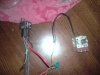
It's hard to tell without touching it myself, but this is how it should be going on the wires in the picture;
The big thick red wire with fuse should go straight to the + batt (positive) terminal.
The thick blue/red will go to one of the thermo fan wires (depending on suck or pull).
Those two are for the fan high current draw, handled by the relay contacts.
Black to vehicle body.
Green is to one of the terminals on the In-Water adjustable Thermo Switch (right of your picture), with a fused wire from other terminal on it to the Ignition + (positive, key switched, not accessory unless you want it on with the radio).
Those two are for the low current for the rely to work.
Then there is the other wire you didn't use on the thermo fan, it goes to the vehicle body or batt - (negative).
Unplug and look at look at the bottom of the relay. The number relate to the diagram on the side of the relay block. In the diagram, there is a coil, two thin wires going to those terminals and the switch diagram (like a ramp) should be the two thick wires.
Before soldering/crimping the two fan wires, check direction of fan rotation for air flow by shorting the green wire directly to the batt + ternial. If wrong, just reverse the two fan wires.
After you have it running at operation temp, be sure to get out, open the bonnet and check for direction of air flow!