Nut Kracker
Donating Member
- Joined
- Oct 18, 2012
- Messages
- 4,760
- Reaction score
- 150
- Points
- 63
- Age
- 64
- Location
- Echuca Vic.
- Members Ride
- VT SS 304ci (195i)
This may have been explained before. Anyway here goes.
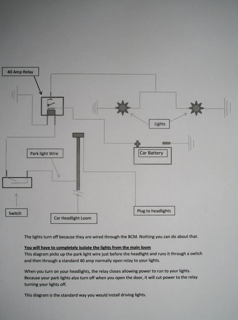
This diagram is can be used to install low powered lights, such as external LED’s or Driving lights.
This diagram suggests that the relay trigger wire be spliced into the “park light wire” in the
Vehicle’s loom.
This is suitable for low powered lights such as external LED’s that you want to come on with the park Lights, low beam and high beam.
If the installation is for driving lights, then the relay trigger wire “must” be connected to the high beam wire in the vehicle’s loom.
This mod incorporates an on/off/on switch that allows the user to switch the lights between coming on with the head lights, having them off and being able to have them on manually.
Other mods are certainly possible with this diagram and it is up to the user to determine which is suitable.
The fuse used in this diagram is for two (2) 55 watt globes. It is up to the user to determine the appropriate size of the fuse for the required application.
This mod may or may not comply with State regulations and it is up to the user to decide as to whether or not to use this mod.
I accept no responsibility for damages caused by installing this mod as it is up to the individual
to decide as to whether or not to use it.
A description is attached to the diagram explaining the mod.
Keep an eye out later on, as I will be posting the ultimate LED wiring diagram for inside your car.

Last edited: