ari666
250,000 hits
- Joined
- Mar 10, 2009
- Messages
- 11,835
- Reaction score
- 128
- Points
- 63
- Location
- melbourne
- Members Ride
- 1966 impala, R32 GTR
a good buddy of mine was stuggling with the concept of a relay and how to get it working properley. ill admit, wiring up 3 relays for + swtiching then one for - switching can easily break your brain, so i thought id write a little reference for others that may be stuggling excuse my MS-paint drawings, but when i went to school we didnt have computers, we drew all this **** by hand.
but first a little introduction to the relay:
a relay is in my opinion one of the singlemost best switching devices ever invented. what it is ideally is a means to run a high current device with a sensitive switch. anyone that has ever worked on an older car with the old headlight-through-switch or even old school ignition switches with the starter wire running through will know what i mean. the high current tends to burn out contacts/wires and anything it comes into contact with, rending the switch useless and expensive to replace.
a relay is a remote device allowing us to keep our sexy switches and not have them catch fire.
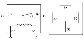
and its a very basic and simple device. you have 4 pins on your average 12V 30A relay. 85-86 and 30-87
now the easiest and best way to think of a relay is a TWO PART CIRCUIT. a circuit, is a means of sending + down a series of wires to - and performing a task in the process, well the relay is sending + in 2 different ways, which are not related. lets take a simple + switched relay, this example will be a high beam activation:

so in this diagram we see that the two seperate circuits are:
original highbeam switch (using + to turn on the device) running to earth via the relay
constant battery + running to the headlights
the way these circuits work is:
(circuit 1)turn the original high beam switch on>sends + to the realy>relay is then energised and closes the switch allowing circuit 2
(circuit 2) relay closes switch> + consant is now able to flow from the battery to the high beams, which makes them illuminate.
capice?
ok, so now we mix it up a bit, we go - switching. sometimes horns are - switched, sometimes starter motors, sometimes headlights.

thats a - switched relay. the switch uses a - signal to energise the relay, so obviously the relay will require a constant + so it has a path to complete the circuit. if you give it a constant earth, itll do bugger all.
so because it has a - trigger, then we assume it needs to pass - to the headlights to make them work, so if its passing negative through the headlights, then of course the other side of the headlights will need + constant/
i suppose i should throw in here that "earth constant" and "+ constant" dont actually need to be constant. there are 3 options, constant, hot (hot to run, ignition, ON, live whatever you wanna call it) or accessories. how you hook it up is all dependant on when you want your "state of charge" if you hook it to constant, and the switch is constant, then itlll work when the ignition is off. etc. a good example is the horn. the horn should work with the ignition off. headlights are neat if you hook the relays up to "hot" so when you kill the engine the lights go off too, so your missus wont run the battery flat while she goes shopping for lipstick.
now these circuits work for ANY powered device, i.e. a fuel pump, windshield wipers, heater fan ANYTHING you can think of where your switch has started to play up, you can hook a relay into and it will provide hooooours of more useful life to it.
now, although your primary circuit, or circuit 1 will remain the same as long as youre using + to switch and - to earth, your secondary circuit can be anything youre heart dreams of, as long as your heart dreams of continuity. for example, a distributor on an old VK V8 uses a pulse or "squarewave" to tell the coil when to fire. its not a + of any kind. its more of an I/O (on off) but that doesnt mean a relay isnt useful. a relay will provide a nice and "clean" signal so you could use it as a theft deterrant

*that cylider thingie next to where is says "battery constant" is meant to be the coil, and its meant to be "ignition" not battery constant*
that right there is a very effective way of disabling your car, and no thief would be the wiser. trust me. no thief would be looking for the signal pulse wire to be removed. they will bypass the power wire, thats easy, but with nothing inbetween the dizzy and the coil, your car aint going nowhere.
and here is a multi circuit i drew for sab who was struggling with his multiple switch rail.
this is a 4 relay "rail" to drive 4 different lights via his dash mounted switches but just to make things tricky, the switches are negative to switch:

now a special word needs to go out to fuses. these circuits are great, but there are no fuses. its always a good idea to fuse any powered devices, but thats entirely up to you and maybe a how-to for another day.
later dudes
Ari
but first a little introduction to the relay:
a relay is in my opinion one of the singlemost best switching devices ever invented. what it is ideally is a means to run a high current device with a sensitive switch. anyone that has ever worked on an older car with the old headlight-through-switch or even old school ignition switches with the starter wire running through will know what i mean. the high current tends to burn out contacts/wires and anything it comes into contact with, rending the switch useless and expensive to replace.
a relay is a remote device allowing us to keep our sexy switches and not have them catch fire.
and its a very basic and simple device. you have 4 pins on your average 12V 30A relay. 85-86 and 30-87
now the easiest and best way to think of a relay is a TWO PART CIRCUIT. a circuit, is a means of sending + down a series of wires to - and performing a task in the process, well the relay is sending + in 2 different ways, which are not related. lets take a simple + switched relay, this example will be a high beam activation:
so in this diagram we see that the two seperate circuits are:
original highbeam switch (using + to turn on the device) running to earth via the relay
constant battery + running to the headlights
the way these circuits work is:
(circuit 1)turn the original high beam switch on>sends + to the realy>relay is then energised and closes the switch allowing circuit 2
(circuit 2) relay closes switch> + consant is now able to flow from the battery to the high beams, which makes them illuminate.
capice?
ok, so now we mix it up a bit, we go - switching. sometimes horns are - switched, sometimes starter motors, sometimes headlights.
thats a - switched relay. the switch uses a - signal to energise the relay, so obviously the relay will require a constant + so it has a path to complete the circuit. if you give it a constant earth, itll do bugger all.
so because it has a - trigger, then we assume it needs to pass - to the headlights to make them work, so if its passing negative through the headlights, then of course the other side of the headlights will need + constant/
i suppose i should throw in here that "earth constant" and "+ constant" dont actually need to be constant. there are 3 options, constant, hot (hot to run, ignition, ON, live whatever you wanna call it) or accessories. how you hook it up is all dependant on when you want your "state of charge" if you hook it to constant, and the switch is constant, then itlll work when the ignition is off. etc. a good example is the horn. the horn should work with the ignition off. headlights are neat if you hook the relays up to "hot" so when you kill the engine the lights go off too, so your missus wont run the battery flat while she goes shopping for lipstick.
now these circuits work for ANY powered device, i.e. a fuel pump, windshield wipers, heater fan ANYTHING you can think of where your switch has started to play up, you can hook a relay into and it will provide hooooours of more useful life to it.
now, although your primary circuit, or circuit 1 will remain the same as long as youre using + to switch and - to earth, your secondary circuit can be anything youre heart dreams of, as long as your heart dreams of continuity. for example, a distributor on an old VK V8 uses a pulse or "squarewave" to tell the coil when to fire. its not a + of any kind. its more of an I/O (on off) but that doesnt mean a relay isnt useful. a relay will provide a nice and "clean" signal so you could use it as a theft deterrant
*that cylider thingie next to where is says "battery constant" is meant to be the coil, and its meant to be "ignition" not battery constant*
that right there is a very effective way of disabling your car, and no thief would be the wiser. trust me. no thief would be looking for the signal pulse wire to be removed. they will bypass the power wire, thats easy, but with nothing inbetween the dizzy and the coil, your car aint going nowhere.
and here is a multi circuit i drew for sab who was struggling with his multiple switch rail.
this is a 4 relay "rail" to drive 4 different lights via his dash mounted switches but just to make things tricky, the switches are negative to switch:
now a special word needs to go out to fuses. these circuits are great, but there are no fuses. its always a good idea to fuse any powered devices, but thats entirely up to you and maybe a how-to for another day.
later dudes
Ari
Last edited:
