cxcxcxvcvcvc
Active Member
- Joined
- Sep 14, 2006
- Messages
- 1,120
- Reaction score
- 16
- Points
- 38
- Location
- The Plains
- Members Ride
- VT Commodore
G,day lads, well been talking with another member on here (VS_pete_1) and he passed on some info on how to upgrade the earth on the o2 sensors, wich is supposed to give better economy ect, well i did it today and while i cannot vouch as yet if i will reap any gains it was not hard to do, and was not expensive! here is a list of the tools/products needed:
*************************************
Solder iron
solder
15amp wire available from repco on a roll for $5 (you will only need one roll as its 4m in length)
EYE connections also from repco about $4
electrical tape
needle nose pliers (for crimping)
side cutters (for cutting wire lol)
and if you have them a pair of wire splicers
allan key to suit top plenum cover bolts
**************************************
Ok here is the instructions sent to me from VS_Pete_1 (your a champion mate:thumbsup: )
#################################################
Remove engine cover – 4 x 10mm nuts.
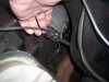
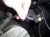
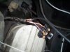
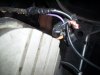
Standing along side LHF guard look down the back of the engine area to locate the o2 sensor in the engine exhaust pie. Follow wires back to the connector and unplug the connector. In the main harness side there will be 4 x wires (2 will be Black).
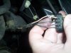
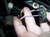
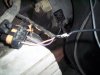
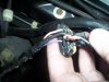
Without cutting wires completely (pain to repair if you do) strip back approx 5mm of insulation on the 2 black wire in the main engine harness. With a separate piece of wire – approx 400 – 500mm long (you will have to buy some unless you have some laying around at home) approx 1 to 1.5mm strip both ends approx 20mm. Twist one end of the new wire around the 2 black ones in the engine harness (the one’s you’ve just striped back) to join all 3 wires together. Solder if you’d like but at least use some electrical tape to cover. Reconnect main harness back to o2 sensor.
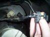
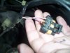
On the other end of the new wire crimp / solder an eye terminal (you’ll have to buy a couple with hole diameter approx 6mm (from memory the allen key bolts into the top of the plenumn cover are approx 5mm in size – double check before buying terminals).
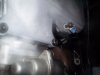
Once terminal fitted to wire remove 1 allen key bolt from plenumn cover (the plate under the engine cover). I’d recommend a bolt closest to the o2 sensor (back rh corner when looking from the front). Fit bolt through eye terminal and retighten bolt – approx 8nm.
Carry out same repairs to drivers side and once done refit engine cover and then drive vehicle as per normal. There is no need to pull BCM fuse out to reset fuel trims etc.
#####################################################
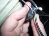
Now when it came for me to do it, i did cut the wires and resoldered them as i found it easier, but each 2 their own") anyway here is some pics to help guide you along!!
anyway here is some pics to help guide you along!!
*************************************
Solder iron
solder
15amp wire available from repco on a roll for $5 (you will only need one roll as its 4m in length)
EYE connections also from repco about $4
electrical tape
needle nose pliers (for crimping)
side cutters (for cutting wire lol)
and if you have them a pair of wire splicers
allan key to suit top plenum cover bolts
**************************************
Ok here is the instructions sent to me from VS_Pete_1 (your a champion mate:thumbsup: )
#################################################
Remove engine cover – 4 x 10mm nuts.
Standing along side LHF guard look down the back of the engine area to locate the o2 sensor in the engine exhaust pie. Follow wires back to the connector and unplug the connector. In the main harness side there will be 4 x wires (2 will be Black).
Without cutting wires completely (pain to repair if you do) strip back approx 5mm of insulation on the 2 black wire in the main engine harness. With a separate piece of wire – approx 400 – 500mm long (you will have to buy some unless you have some laying around at home) approx 1 to 1.5mm strip both ends approx 20mm. Twist one end of the new wire around the 2 black ones in the engine harness (the one’s you’ve just striped back) to join all 3 wires together. Solder if you’d like but at least use some electrical tape to cover. Reconnect main harness back to o2 sensor.
On the other end of the new wire crimp / solder an eye terminal (you’ll have to buy a couple with hole diameter approx 6mm (from memory the allen key bolts into the top of the plenumn cover are approx 5mm in size – double check before buying terminals).
Once terminal fitted to wire remove 1 allen key bolt from plenumn cover (the plate under the engine cover). I’d recommend a bolt closest to the o2 sensor (back rh corner when looking from the front). Fit bolt through eye terminal and retighten bolt – approx 8nm.
Carry out same repairs to drivers side and once done refit engine cover and then drive vehicle as per normal. There is no need to pull BCM fuse out to reset fuel trims etc.
#####################################################
Now when it came for me to do it, i did cut the wires and resoldered them as i found it easier, but each 2 their own
anyway here is some pics to help guide you along!!