ephect
Donating Member
- Joined
- Jul 27, 2006
- Messages
- 5,920
- Reaction score
- 15,537
- Points
- 113
- Location
- Melbourne
- Members Ride
- VS Acclaim V6
More Pictures will be added later, this is all i have so far...
DISCLAIMER: This a guide only, by following this process I take no responsibility what so ever. If you bodge it, fry your ECU or your car turns into a troll and consumes your insides. You do so at your own risk. Now with the formalities out the way... let’s begin
The Problem: The 4 wire oxygen sensors include an internal heater, which aids the sensor to reach operating temperature quicker than relying on the exhaust to heat up the sensor. The heater circuit interferes with the signal received by the ECU from the 02 circuit, due to both circuits sharing the earth. This is the main fault for increased fuel consumption, and often fault codes logged:
Code 44 - RH Oxygen Sensor Lean (O2)
Code 45 - RH Oxygen Sensor Rich (O2)
Code 64 - LH Oxygen Sensor Lean (O2)
Code 65 - LH Oxygen Sensor Rich (O2)
Code 76 - Air/Fuel ratio variation between left and right banks
Code 78 - Air/Fuel ratio variation between left and right banks
The Solution: To earth both circuits to a good solid earth point on the chassis somewhere, then replace both existing O2 sensors with genuine new items. Even if you have recently installed new O2 sensors, these might have been prematurely failed without logging an exact code. If you want to see the full benefit of this fix, replace your O2 sensors after completing the earth fix. Example: I completed the earth fix, drove around for 2 weeks prior to installing the new O2 sensors and my air/fuel gauge showed varied results, immediately after installing new O2 sensors instant readings of 14.7 displayed.
This guide recommends new O2 sensors with the fix.
This guide replaces the need to cut the pink wire! if you have cut the pink wire, my advice is to follow this guide and fix the issue properly.
What’s needed:
* Common Sense, I know we all have some
* Soldering iron & solder
* 10cm length of wire
* 50cm length of wire
* Side cutters
* Small pointy nose pliers
* Stanley knife or blade.
* 1x Ring electrical connector (crimps on wire and looks like a loop/washer)
* Electrical tape (normally I would suggest Heat shrink, but we aren’t cutting wires)
* Screw drivers both flat and star
* 2x New Genuine O2 sensors: Part #25312184
* Couple hours and a couple of cans
Here’s how to fix up the earthing issue
Gaining access to the ECU
* Undo the 3-4 plastic screws underneath the glovebox between it and the firewall.
* Open the glovebox
* Remove the black pin on the right hand side
* Gently remove the glovebox compartment.
* Open the passengers door,
* Unscrew the 3 screws in the vent (dash side, not the door vents) and 1 screw visable under the end of the dash where the glovebox hinges on the left hand side.
* Using a small screw driver, lift the beeding on the door sill and peel it back about a foot.
* Gently remove the kick panel by pull the bottom in the centre, the back will pop out first, then prise the door seal out a little to let the side of the kick panel out. Lift the sill panel up and the kick panel should pull away.
* using the small flat blade screw driver, lift the tabs at the sides and bottom of the ECU to release it from its holder.
Fixing the Earth at the ECU
Disconnect your Negative Battery Terminal prior to carrying out any electrical work.
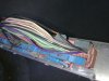
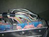
* locate 3 black wires
- 2 wires on 32pin blue plug, pink socket – D14 and D16
- 1 wire on 24pin blue plug, pink socket – A2

* Strip the 3 wires back using a blade by ringing the insulation (slicing around) in one spot, then ringing it again 5-8mm below it. Then u can slice along the wire from ring to ring and peel that section out.

* Get your 10cm wire and strip 10mm from both ends
* Get your 50cm wire and strip 10mm from both ends
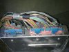
* Twist one end of both 10cm & 50cm together (don’t solder yet)
* Twist your joined wires around both D14 and D16.
* Solder the 4 wires, then wrap with electrical tape.

* Wrap the other end of 10cm wire around wire A2
* Solder this together and wrap with electrical tape.

* Crimp on the loop crimp on electrical connector to the other end of the 50cm wire and solder the wire to the connector for good measure.
* Locate an earth point on the chassis, clean it and then screw the loop connector firm.
Put back the kick panel and glove box together by reversal of the above. Install your new O2 sensors and your done!
References: I have results and all pre testing prior to providing this how-to in this thread: http://forums.justcommodores.com.au/vr-vs-holden-commodore-1993-1997/92957-too-lean-one-bank.html
Cheers
ephect
.
DISCLAIMER: This a guide only, by following this process I take no responsibility what so ever. If you bodge it, fry your ECU or your car turns into a troll and consumes your insides. You do so at your own risk. Now with the formalities out the way... let’s begin
The Problem: The 4 wire oxygen sensors include an internal heater, which aids the sensor to reach operating temperature quicker than relying on the exhaust to heat up the sensor. The heater circuit interferes with the signal received by the ECU from the 02 circuit, due to both circuits sharing the earth. This is the main fault for increased fuel consumption, and often fault codes logged:
Code 44 - RH Oxygen Sensor Lean (O2)
Code 45 - RH Oxygen Sensor Rich (O2)
Code 64 - LH Oxygen Sensor Lean (O2)
Code 65 - LH Oxygen Sensor Rich (O2)
Code 76 - Air/Fuel ratio variation between left and right banks
Code 78 - Air/Fuel ratio variation between left and right banks
The Solution: To earth both circuits to a good solid earth point on the chassis somewhere, then replace both existing O2 sensors with genuine new items. Even if you have recently installed new O2 sensors, these might have been prematurely failed without logging an exact code. If you want to see the full benefit of this fix, replace your O2 sensors after completing the earth fix. Example: I completed the earth fix, drove around for 2 weeks prior to installing the new O2 sensors and my air/fuel gauge showed varied results, immediately after installing new O2 sensors instant readings of 14.7 displayed.
This guide recommends new O2 sensors with the fix.
This guide replaces the need to cut the pink wire! if you have cut the pink wire, my advice is to follow this guide and fix the issue properly.
What’s needed:
* Common Sense, I know we all have some
* Soldering iron & solder
* 10cm length of wire
* 50cm length of wire
* Side cutters
* Small pointy nose pliers
* Stanley knife or blade.
* 1x Ring electrical connector (crimps on wire and looks like a loop/washer)
* Electrical tape (normally I would suggest Heat shrink, but we aren’t cutting wires)
* Screw drivers both flat and star
* 2x New Genuine O2 sensors: Part #25312184
* Couple hours and a couple of cans
Here’s how to fix up the earthing issue
Gaining access to the ECU
* Undo the 3-4 plastic screws underneath the glovebox between it and the firewall.
* Open the glovebox
* Remove the black pin on the right hand side
* Gently remove the glovebox compartment.
* Open the passengers door,
* Unscrew the 3 screws in the vent (dash side, not the door vents) and 1 screw visable under the end of the dash where the glovebox hinges on the left hand side.
* Using a small screw driver, lift the beeding on the door sill and peel it back about a foot.
* Gently remove the kick panel by pull the bottom in the centre, the back will pop out first, then prise the door seal out a little to let the side of the kick panel out. Lift the sill panel up and the kick panel should pull away.
* using the small flat blade screw driver, lift the tabs at the sides and bottom of the ECU to release it from its holder.
Fixing the Earth at the ECU
Disconnect your Negative Battery Terminal prior to carrying out any electrical work.
* locate 3 black wires
- 2 wires on 32pin blue plug, pink socket – D14 and D16
- 1 wire on 24pin blue plug, pink socket – A2
* Strip the 3 wires back using a blade by ringing the insulation (slicing around) in one spot, then ringing it again 5-8mm below it. Then u can slice along the wire from ring to ring and peel that section out.
* Get your 10cm wire and strip 10mm from both ends
* Get your 50cm wire and strip 10mm from both ends
* Twist one end of both 10cm & 50cm together (don’t solder yet)
* Twist your joined wires around both D14 and D16.
* Solder the 4 wires, then wrap with electrical tape.
* Wrap the other end of 10cm wire around wire A2
* Solder this together and wrap with electrical tape.
* Crimp on the loop crimp on electrical connector to the other end of the 50cm wire and solder the wire to the connector for good measure.
* Locate an earth point on the chassis, clean it and then screw the loop connector firm.
Put back the kick panel and glove box together by reversal of the above. Install your new O2 sensors and your done!
References: I have results and all pre testing prior to providing this how-to in this thread: http://forums.justcommodores.com.au/vr-vs-holden-commodore-1993-1997/92957-too-lean-one-bank.html
Cheers
ephect
.
Attachments
Last edited:
")