- Joined
- Apr 15, 2006
- Messages
- 22,586
- Reaction score
- 20,368
- Points
- 113
- Location
- Sth Auck, NZ
- Members Ride
- HSV VS Senator, VX Calais II L67
for those that are running shorter diff ratios or have fitted larger wheels and the speedo is reading a little faster (or sometimes a lot depending on gears used) here is a simple way to fix this problem
parts required:
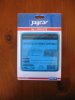
speedo corrector kit available from Jaycar for about $60 pic 1
UB3 jiffy box, $4.50 approx from jaycar
heatshrink
some sort of cold beverage
tools required:
soldering iron
cutters
fine screw driver
wire stripper
a little patience
time:
3-4hrs to complete job depending on how good/familiar you are at electrical/electronics/wiring
assemble the kit as per instructions supplied with the kit, these instructions are very detailed, give a full breakdown of all the parts and how to identify them if your not familiar with electrical components. i recomend using a quality soldering iron with controlled temperature, the cheapy 25w irons just lack a little heat to solder things quickly. i recomend starting to assemble form either the center of the PCB or one end and work your way out as some of the components are quiet close and you don't want to solder a link accross the different tracks on the PCB.
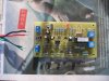
I've tinned the end of each of the 4 wires supplied in the kit and then wrapped approx half in black tape like a regular wiring loom. pic 2
once the kit is complete it's time to fit it in the car
first you need to remove the center console and facia around the stereo, now most of you should be familair with this as i'm guessing most will have installed there own stereo gear, for those that haven't.
1. you need to lift the cover over the gear selector and move it as far down as possible. for a manual gearbox, simply unscrew the gear selector know and lift entire cover off and hang out the way in the passanger footwell. for an auto, disconnect the wiring from the bottom of the siggy lighter and move shifter into the 1 position.
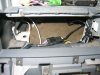
2. remove the 3 screws at the bottom of the center facia and gently pull it away from around the stereo and aircon controls. it should like something like this - pic 3
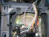
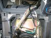
now you need to free the wiring loom thats under the console and find the wire that we need to cut and splice the speedo corrector kit into. the wire we are after is purple with a white trace. i have unplugged the loom and unwrapped the loom about 200mm. pic 4
to confirm this was the wire coming from the sender unit on the gearbox i simply removed the pin for this wire from the plug, connected the loom back together and went for a quick spin, no speedo confirmed that i had the right wire. assume that i'm a complete mug at this time and check it for yourself")
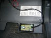
choose a location for your speedo corrector. i have chosen to mount mine by the fuse panel. i intend to get some velcro backed tape so that it will not move about when driving. with the vecro and extended wiring loom that i have allowed for if in the future i need to adjust my setting i will be able to drop the fuse panel cover down, remove box from velcro and get into the box without needing to get my head under the steering wheel. makes it easy to have a passenger make adjustments whilst you drive also. pic 5
pull the 2 wires through to the exsisting loom we are going to splice into. make sure the wire coming from the sender goes to input side of the speedo corrector kit and output goes to the speedo etc. twist wires together and solder together (don't forget to slip heat shrink over the wires first). it should look something like this. pic 6
tape loom up and plug loom back in. put back in orignal position under console. refit facia and gear selector covers etc
find a good eath point and wire +12volts from an iginition switched source.
now it's time to calibrate the speedo corrector kit. again the kit instructions cover this in detail
1. set S1 to 2
2. set S2 to A
3. install LK2 (link, marked on PCB)
4. drive car, speedo won't work (this is normal, i only had to back about 25m in my driveway for this part)
5. LED should flash at 1hz (once per second when it's self calibrated for the incoming signal)
6. set S1 to 0
7. set S2 to 0
8. intall LK3 (link ,marked on PCB, this is the setting i have used)
the speedo should now read as it did before installing the speedo corrector kit was fitted. now you can use S1 & S2 to select correction required. S1 for single units, S2 for tens
to calculate the % difference between you original gears (3.08) and new gears ( i have 3.45) use this simple formula
old ratio/new ratiox100 or 3.08/3.45x100=89.3%
so the old ratio is reading @ 89.3% of the new ratio or 100-89.3=10.7% correction.
i've set mine to 10% (S2 to 1) and over a 5km odo test my odo was less then 300 meters out so it's fairly close (this also shows that holden calibrates there speedo's to read slightly faster then your actually travelling)
if you wish to make an adjustment for different tyre sizes go to this website
TYRESAVE: Tyre Speed Ratings
and use there tyre size calculator (at bottom of there page)to work out the difference between your old tyres and new ones (it gives a % difference as well as actaull size in mm)
final calibration instructions taken inpart from speedo corrector kit instructions - jaycar
parts required:
speedo corrector kit available from Jaycar for about $60 pic 1
UB3 jiffy box, $4.50 approx from jaycar
heatshrink
some sort of cold beverage
tools required:
soldering iron
cutters
fine screw driver
wire stripper
a little patience
time:
3-4hrs to complete job depending on how good/familiar you are at electrical/electronics/wiring
assemble the kit as per instructions supplied with the kit, these instructions are very detailed, give a full breakdown of all the parts and how to identify them if your not familiar with electrical components. i recomend using a quality soldering iron with controlled temperature, the cheapy 25w irons just lack a little heat to solder things quickly. i recomend starting to assemble form either the center of the PCB or one end and work your way out as some of the components are quiet close and you don't want to solder a link accross the different tracks on the PCB.
I've tinned the end of each of the 4 wires supplied in the kit and then wrapped approx half in black tape like a regular wiring loom. pic 2
once the kit is complete it's time to fit it in the car
first you need to remove the center console and facia around the stereo, now most of you should be familair with this as i'm guessing most will have installed there own stereo gear, for those that haven't.
1. you need to lift the cover over the gear selector and move it as far down as possible. for a manual gearbox, simply unscrew the gear selector know and lift entire cover off and hang out the way in the passanger footwell. for an auto, disconnect the wiring from the bottom of the siggy lighter and move shifter into the 1 position.
2. remove the 3 screws at the bottom of the center facia and gently pull it away from around the stereo and aircon controls. it should like something like this - pic 3
now you need to free the wiring loom thats under the console and find the wire that we need to cut and splice the speedo corrector kit into. the wire we are after is purple with a white trace. i have unplugged the loom and unwrapped the loom about 200mm. pic 4
to confirm this was the wire coming from the sender unit on the gearbox i simply removed the pin for this wire from the plug, connected the loom back together and went for a quick spin, no speedo confirmed that i had the right wire. assume that i'm a complete mug at this time and check it for yourself
choose a location for your speedo corrector. i have chosen to mount mine by the fuse panel. i intend to get some velcro backed tape so that it will not move about when driving. with the vecro and extended wiring loom that i have allowed for if in the future i need to adjust my setting i will be able to drop the fuse panel cover down, remove box from velcro and get into the box without needing to get my head under the steering wheel. makes it easy to have a passenger make adjustments whilst you drive also. pic 5
pull the 2 wires through to the exsisting loom we are going to splice into. make sure the wire coming from the sender goes to input side of the speedo corrector kit and output goes to the speedo etc. twist wires together and solder together (don't forget to slip heat shrink over the wires first). it should look something like this. pic 6
tape loom up and plug loom back in. put back in orignal position under console. refit facia and gear selector covers etc
find a good eath point and wire +12volts from an iginition switched source.
now it's time to calibrate the speedo corrector kit. again the kit instructions cover this in detail
1. set S1 to 2
2. set S2 to A
3. install LK2 (link, marked on PCB)
4. drive car, speedo won't work (this is normal, i only had to back about 25m in my driveway for this part)
5. LED should flash at 1hz (once per second when it's self calibrated for the incoming signal)
6. set S1 to 0
7. set S2 to 0
8. intall LK3 (link ,marked on PCB, this is the setting i have used)
the speedo should now read as it did before installing the speedo corrector kit was fitted. now you can use S1 & S2 to select correction required. S1 for single units, S2 for tens
to calculate the % difference between you original gears (3.08) and new gears ( i have 3.45) use this simple formula
old ratio/new ratiox100 or 3.08/3.45x100=89.3%
so the old ratio is reading @ 89.3% of the new ratio or 100-89.3=10.7% correction.
i've set mine to 10% (S2 to 1) and over a 5km odo test my odo was less then 300 meters out so it's fairly close (this also shows that holden calibrates there speedo's to read slightly faster then your actually travelling)
if you wish to make an adjustment for different tyre sizes go to this website
TYRESAVE: Tyre Speed Ratings
and use there tyre size calculator (at bottom of there page)to work out the difference between your old tyres and new ones (it gives a % difference as well as actaull size in mm)
final calibration instructions taken inpart from speedo corrector kit instructions - jaycar
Attachments
-
 speedo corrector kit 005.jpg77.1 KB · Views: 4,725
 -
 speedo corrector kit 003.jpg122.6 KB · Views: 5,629
 -
 speedo corrrector kit wiring 004.jpg93.2 KB · Views: 4,156
 -
 speedo corrrector kit wiring 001.jpg120.9 KB · Views: 7,195
 -
 speedo corrrector kit wiring 005.jpg89.6 KB · Views: 5,023
 -
 speedo corrrector kit wiring 003.jpg126.6 KB · Views: 5,106
Last edited: