Welcome to Just Commodores, a site specifically designed for all people who share the same passion as yourself.

New Posts Contact us

Just Commodores Forum Community

It takes just a moment to join our fantastic community

Register

VN Calais Trip Comp Plug

Lexx

New Member
Joined
Jan 3, 2005
Messages
457
Reaction score
3
Points
0
Location
Sydney
Members Ride
VT II S/C S
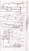
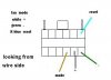
Has anyone got pics of the plug, or the exact locations of the wires in the plug, for the trip computer switch on a VN Calais?
I've seen the diagrams on this site but they are mostly for the VS set up, not VN.
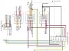
This is where I'm at so far. If anyone can help fill in the blanks, I'd be greatful. :w00t:
Once complete I'll list the diagram for other VN users to use to do the same mod.

(Thanks to user samovp for letting me ummm, borrow and modify his wiring diagram. It can be found HERE :thumbsup: )​
 

Attachments

  • My VN dash wiring.jpg
    My VN dash wiring.jpg
    200 KB · Views: 783
Last edited:

markovr

Well-Known Member
Joined
Nov 23, 2003
Messages
3,072
Reaction score
252
Points
83
Age
62
Location
northside brisbane
Website
youtu.be
Members Ride
07vessv 94vr .04vz wgn,93vp wgn,82 vhV6 wgn 88 vn

Lexx

New Member
Joined
Jan 3, 2005
Messages
457
Reaction score
3
Points
0
Location
Sydney
Members Ride
VT II S/C S
markovr said:
Ive done it to my vp..not sure how different to vn but I imagine not much.
Check out this attachment
http://forums.justcommodores.com.au/attachment.php?attachmentid=2052

markovr, I was already using the linked diagram to get to the stage I'm at. Thanks for your help on that. The diagram has been a great help so far.
However, it is not correct for the VN. I have the 3 main dash plugs here from a VN Calais loom and found some differences between them, my VN Berlina and your VP diagram. The differences I have found so far are:
  • Number 15: Connector 4 terminal 15, black/white soldered to black on connector 3 terminal 9
    The black wire on connector 3 terminal 9 is not there on my VN Berlina or the VN Calais loom
  • Number 17: Connector 4 terminal 17 Lt blue goes across to switch block connector
    If I put the Lt Blue wire from connector 4 terminal 17 in your suggested position on the switch block connector, I'd have to remove a grey wire currently in that position
Then there's the YB66 connector:
  • Number 4: A green wire is soldered to green wire on Connector 3 (YB68) terminal 8 and goes to Connector 1 terminal 9
    On my VN Berlina the green wire in connector 3 (YB68) terminal 8 is not there. However there is one on the VN Calais loom. What do I do for this wire?
At that point it was getting on in the afternoon and getting cold so I left it at that for now to come in and start trying to figure out the differences and how to add the missing wires.
Once I have it sorted, with the great help of forum members, I'll post up the completed diagram :thumbsup:
 

markovr

Well-Known Member
Joined
Nov 23, 2003
Messages
3,072
Reaction score
252
Points
83
Age
62
Location
northside brisbane
Website
youtu.be
Members Ride
07vessv 94vr .04vz wgn,93vp wgn,82 vhV6 wgn 88 vn
Lexx said:
[*]Number 15: Connector 4 terminal 15, black/white soldered to black on connector 3 terminal 9
The black wire on connector 3 terminal 9 is not there on my VN Berlina or the VN Calais loom
[*]Number 17: Connector 4 terminal 17 Lt blue goes across to switch block connector
If I put the Lt Blue wire from connector 4 terminal 17 in your suggested position on the switch block connector, I'd have to remove a grey wire currently in that position
[/list]
Then there's the YB66 connector:
  • Number 4: A green wire is soldered to green wire on Connector 3 (YB68) terminal 8 and goes to Connector 1 terminal 9
    On my VN Berlina the green wire in connector 3 (YB68) terminal 8 is not there. However there is one on the VN Calais loom. What do I do for this wire?
At that point it was getting on in the afternoon and getting cold so I left it at that for now to come in and start trying to figure out the differences and how to add the missing wires.
Once I have it sorted, with the great help of forum members, I'll post up the completed diagram :thumbsup:
Firstly the black/white wire is a body earth and any wire that is that colour or just black will be ok to tee off
The wiring for the switchblocks are different between the two models and I think due to the interior light delay in the vp the positioning of the wires in the connectors is different
The green wire mod is so the idiot light for press remote is in the right position...again it applies to a vp with the theft deterent module which a vn in most cases doesnt have.
This is a vn wiring for l3 dash.
 

Attachments

  • inst circuit.jpg
    inst circuit.jpg
    340.9 KB · Views: 3,534
Last edited:

Lexx

New Member
Joined
Jan 3, 2005
Messages
457
Reaction score
3
Points
0
Location
Sydney
Members Ride
VT II S/C S
markovr said:
Firstly the black/white wire is a body earth and any wire that is that colour or just black will be ok to tee off
The wiring for the switchblocks are different between the two models and I think due to the interior light delay in the vp the positioning of the wires in the connectors is different
The green wire mod is so the idiot light for press remote is in the right position...again it applies to a vp with the theft deterent module which a vn in most cases doesnt have.
This is a vn wiring for l3 dash.
If that's the case, I just have to join the last Black/White to same and the cluster's done.
Just have to get the switch block connector figured out correctly. I saved the wiring diagram ( thanks for that ) but it is unreadable in its current size.
 

markovr

Well-Known Member
Joined
Nov 23, 2003
Messages
3,072
Reaction score
252
Points
83
Age
62
Location
northside brisbane
Website
youtu.be
Members Ride
07vessv 94vr .04vz wgn,93vp wgn,82 vhV6 wgn 88 vn
Lexx said:
If that's the case, I just have to join the last Black/White to same and the cluster's done.
Just have to get the switch block connector figured out correctly. I saved the wiring diagram ( thanks for that ) but it is unreadable in its current size.
Cant you save it and then zoom in on it to read it.
Ive got a vn switchblock circuitboard spare and this is how the trip buttons wires are setup looking from the wire side of connector.
 

Attachments

  • trip connector.JPG
    trip connector.JPG
    9.3 KB · Views: 548
Last edited:

Lexx

New Member
Joined
Jan 3, 2005
Messages
457
Reaction score
3
Points
0
Location
Sydney
Members Ride
VT II S/C S
markovr said:
Cant you save it and then zoom in on it to read it.
Was the first thing I tried. Photo Chop cant even help me with that one.
I'll wire my switch up as per the one you have and hope for the best. :thumbsup:
 

markovr

Well-Known Member
Joined
Nov 23, 2003
Messages
3,072
Reaction score
252
Points
83
Age
62
Location
northside brisbane
Website
youtu.be
Members Ride
07vessv 94vr .04vz wgn,93vp wgn,82 vhV6 wgn 88 vn
I enlarged the circuit diagram above..see if that helps
 

Lexx

New Member
Joined
Jan 3, 2005
Messages
457
Reaction score
3
Points
0
Location
Sydney
Members Ride
VT II S/C S
markovr said:
I enlarged the circuit diagram above..see if that helps
It did indeed. Thanks. :D
 

diagonal sleeper

New Member
Joined
Sep 5, 2005
Messages
60
Reaction score
0
Points
0
so, correct me if im wrong.... to get jst the odo working i would need to connect both 12v + & earths, speed sensor, and lighting for night time?
 
Top