Welcome to Just Commodores, a site specifically designed for all people who share the same passion as yourself.

New Posts Contact us

Just Commodores Forum Community

It takes just a moment to join our fantastic community

Register

Converting VN to Climate Control

ashleysnep

Donating Member
Joined
Jun 10, 2005
Messages
1,061
Reaction score
11
Points
38
Location
Ruse, NSW
Members Ride
355 VN GRP A REP
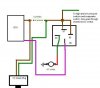
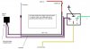
Yeah, right now i got the light green and the yellow/black controling the relay switching the earth for the fan.

I followed the instruction's and use these http://forums.justcommodores.com.au/988326-post63.html pictures as a guide.

I dont see how wiring the relay any differently will change anything? Would that thing that replaced the fan speed resister have anything to do with it?

I assumed the relay only came in when the fan was on full speed, which is what its doing now. When on 1 or 2 speed 12v is run though the 3rd connecter near the fan thats connected to the 12v of the fan. (thats a guess)

Oh well almost there :) Shouldnt of tryed this while installing a alram, pwr windows and mirrors and central locking, wires everywhere!!!
 

Robert Cowland

New Member
Joined
Sep 17, 2009
Messages
9
Reaction score
0
Points
0
Location
Mt Gambier
Members Ride
1952 Chevy
What sensors where?

G'day
just a quick question, as posted by me a few days ago in another post, VP CLIMATE CONTROL WIRING DIAGRAM, I know which sensor goes on the air cond core in the box , but where is the other two go? one has a probe with 2 retaining screws, the other a flat end, any pics would be handy as i no longer have the origanal heater box.
Thanks Robert
 

ashleysnep

Donating Member
Joined
Jun 10, 2005
Messages
1,061
Reaction score
11
Points
38
Location
Ruse, NSW
Members Ride
355 VN GRP A REP
Filled the car up with coolant and gave the climate a proper test, everything works but the 1, 2 speed. But im putting the dash back in cause i can fix that later (need the car)

Also i just remembered, i got a dark green wire that i ran to the engine bay for the ac relay, this wasent in the instructions but i think i looked it up in the manual. Sounds right?
 

88GreenVN

Next Exit Left
Joined
Jun 12, 2006
Messages
6,795
Reaction score
136
Points
63
Age
60
Location
Surprise, Arizona
Members Ride
Dodge Ram Van 1500 5.2 V8
G'day
just a quick question, as posted by me a few days ago in another post, VP CLIMATE CONTROL WIRING DIAGRAM, I know which sensor goes on the air cond core in the box , but where is the other two go? one has a probe with 2 retaining screws, the other a flat end, any pics would be handy as i no longer have the origanal heater box.
Thanks Robert

1 sensor is the sun sensor and goes to the top middle part of the dash.
2 is the ambient temp sensor and that goes to the front of the car down by the radiator or inside the front bumper.
3 is the inside sensor and that is at the bottom of the control unit and has the little square tube that slots into it whan fitting the control unit.
4 goes inside the condencer inside the heater box
5 is the water temp sensor ant that clips onto the copper tube.
 

88GreenVN

Next Exit Left
Joined
Jun 12, 2006
Messages
6,795
Reaction score
136
Points
63
Age
60
Location
Surprise, Arizona
Members Ride
Dodge Ram Van 1500 5.2 V8
Filled the car up with coolant and gave the climate a proper test, everything works but the 1, 2 speed. But im putting the dash back in cause i can fix that later (need the car)

Also i just remembered, i got a dark green wire that i ran to the engine bay for the ac relay, this wasent in the instructions but i think i looked it up in the manual. Sounds right?

Bottom line is the climate system is very different to the standard system with the fan going the wrong way. We spen the better part of 2 weeks working the wiring out and it's very much the way the relay is wired. I did this last xmas so I'm a positive on how we did the wires - but felt that I had the point no 25 correct. A few others have done the mod and got the 3 fan speeds working.

So I would go back over the relay wires and see how you go. :thumbsup:
 

Robert Cowland

New Member
Joined
Sep 17, 2009
Messages
9
Reaction score
0
Points
0
Location
Mt Gambier
Members Ride
1952 Chevy
Thanks for the info on where the sensors go should be able to finish making the custom box
cheers Robert
 

ashleysnep

Donating Member
Joined
Jun 10, 2005
Messages
1,061
Reaction score
11
Points
38
Location
Ruse, NSW
Members Ride
355 VN GRP A REP
What about the green wire? Is it to switch the relay for the compressor? If not what controls the compressor?

Havent tryed them yet since there's no gas i dissconected the compressor.
 

keza87

JCCC NSW Member
Joined
May 15, 2006
Messages
245
Reaction score
2
Points
18
Age
37
Location
Sydney
Members Ride
VX/VY/VZ Wagon LS1
Mischa,
I have found my wiring diagram from when I did mine.
For the fan, how did you wire it? Positive to the fan should come from the engine bay. This was an additional wire that I used. Negative to the fan should come from the fan relay. I.E. opposite to what the old wiring was. The fan speed resistor controller should get negative power instead of positive.

The wire that you have left over is that Green or is it Green/Black?
 

ashleysnep

Donating Member
Joined
Jun 10, 2005
Messages
1,061
Reaction score
11
Points
38
Location
Ruse, NSW
Members Ride
355 VN GRP A REP
The fan is wired so the relay is switching earth to the fan and the resister, and 12v constant from the batt. The relay is being switch by the yellow/black and green, no idea where the green goes but thats what the instruction said to connect it to. So im stuffed as to what it is.

Well i had 10 wires come from the green adapter, everything else ive read said all it should be is 10. Anyway its only green and its a dark green. What controls the ac relay anyway?

Everything works fine apart from 1, 2 speed and ac relay. Im happy i just got the car 'legaly' drivable :p
 

ashleysnep

Donating Member
Joined
Jun 10, 2005
Messages
1,061
Reaction score
11
Points
38
Location
Ruse, NSW
Members Ride
355 VN GRP A REP
First picture is how ive wired the AC relay, cant test this yet cause there's no gas.

Second i how ive wired the blower motor and relay, I cant see whats wrong?
 

Attachments

  • CC air con switch.JPG
    CC air con switch.JPG
    23.7 KB · Views: 3,167
  • CC blower motor.JPG
    CC blower motor.JPG
    35.7 KB · Views: 2,522
Last edited:
Top