OS-Mike
New Member
- Joined
- Jul 12, 2011
- Messages
- 48
- Reaction score
- 0
- Points
- 0
- Age
- 38
- Location
- New Zealand (Tauranga)
- Members Ride
- VZ SV6
So iv got a few weeks of holidays coming up and i know ill get board not working on cars all day so im going to make some extractors custom made for my engine to learn something new iv never really looked at the science behind extractors and iv spent 3h a night for the last 3 nights collecting raw data calculating and designing and its making my head hurt so i give up for tonight lol. But i can tell you there is not one set of properly made extractors for an alloytec 190 not even the pacemaker "tuned length" ones they dont even look close and what exactly are they tuned for? i have seen one nice set for a 335hp camaro but the dimensions are to big for alloytec190's ill add a pic at the bottom of post.
Is there any engineers out there (not the welding or fabricating kind) or exhaust gurus that can help with some numbers i think iv got it right but this engine is a nightmare to calculate the ideal length for the pressure wave's due to cam phasing.
Design goals: Its a street car so broad torque curve with peak pressure wave efficiency at 4500rpm-5000rpm in theory about -3 to -5 psi at the exhaust valve.
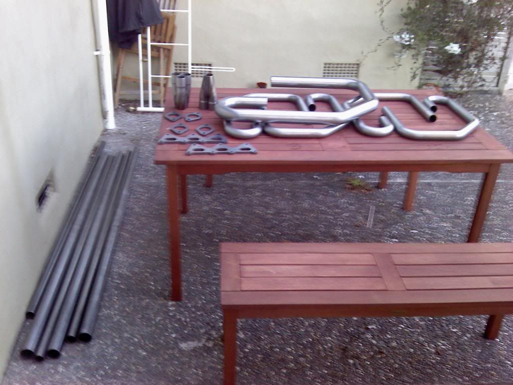
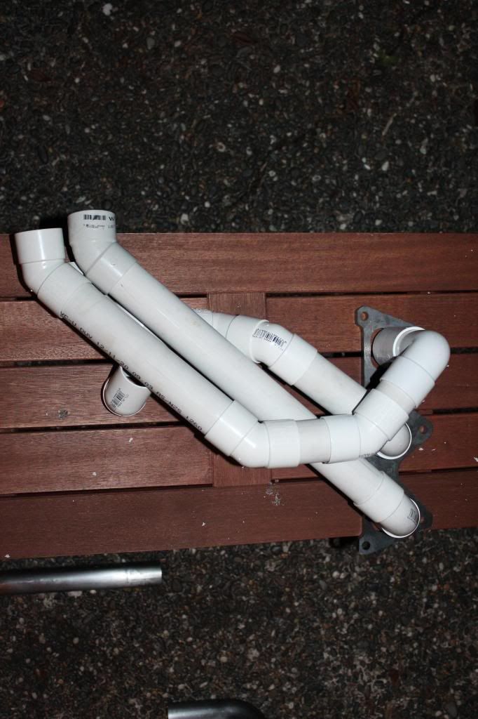
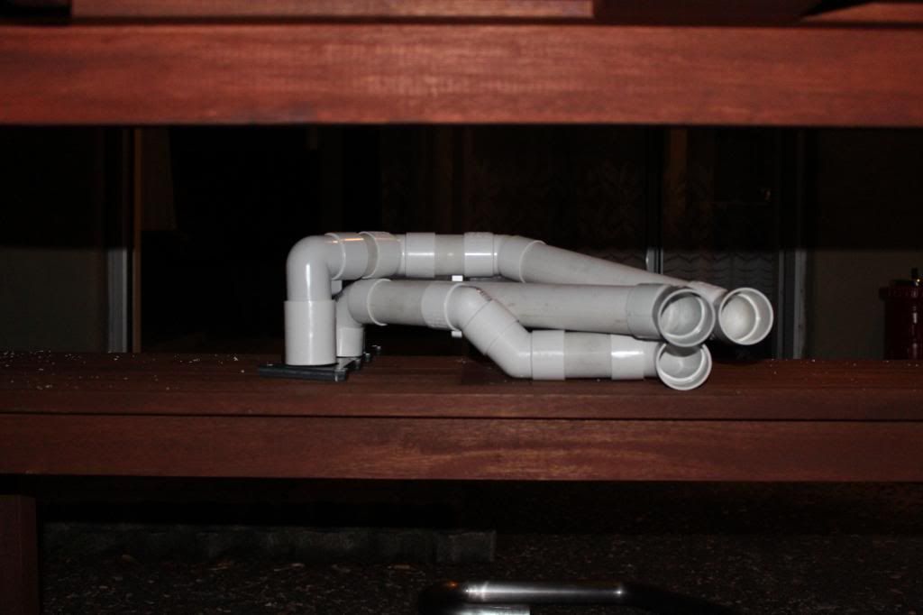
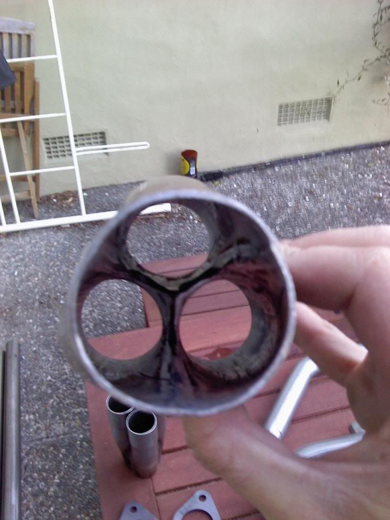
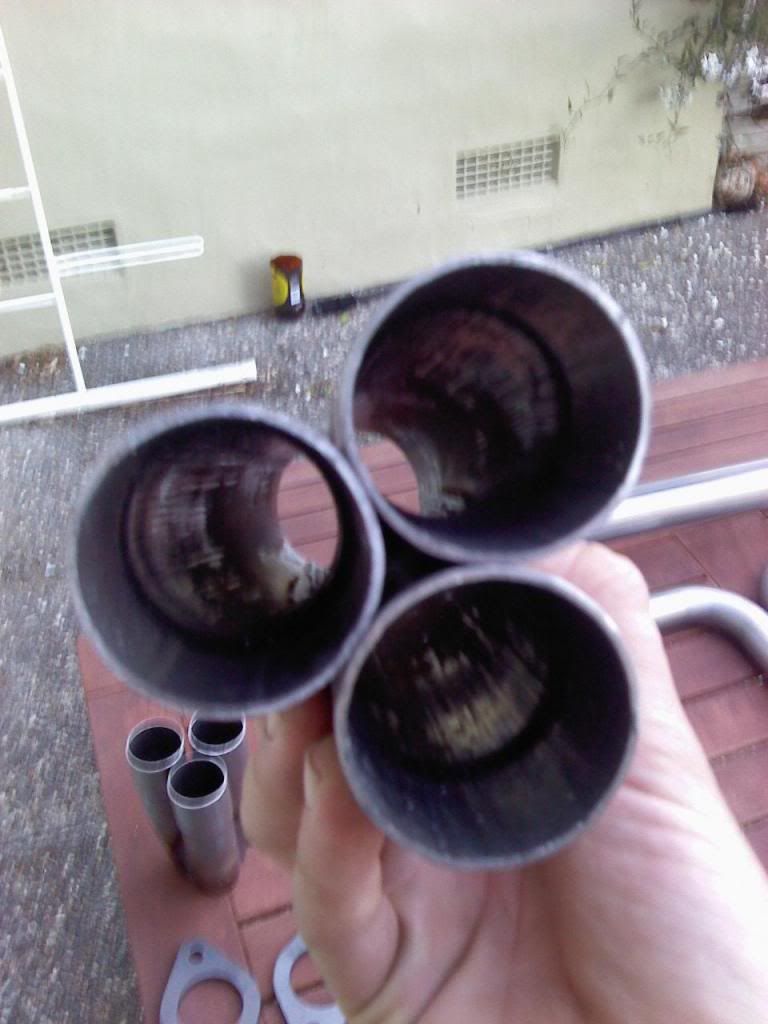
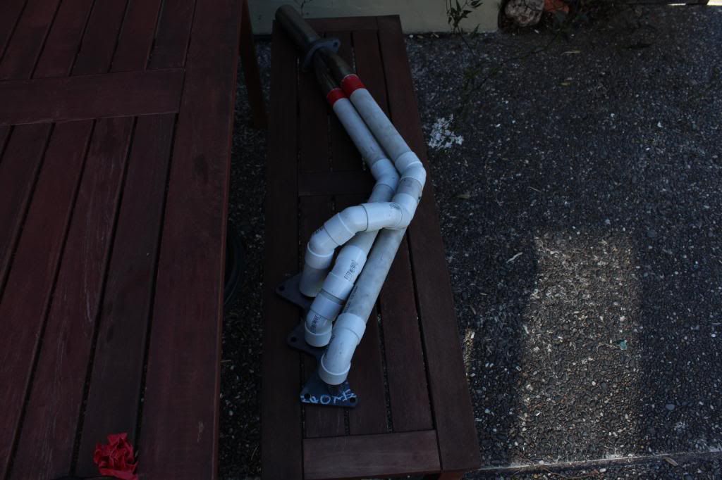
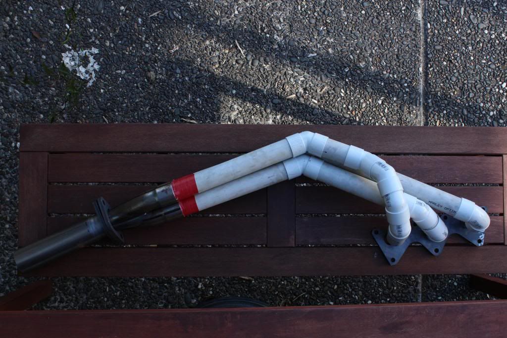
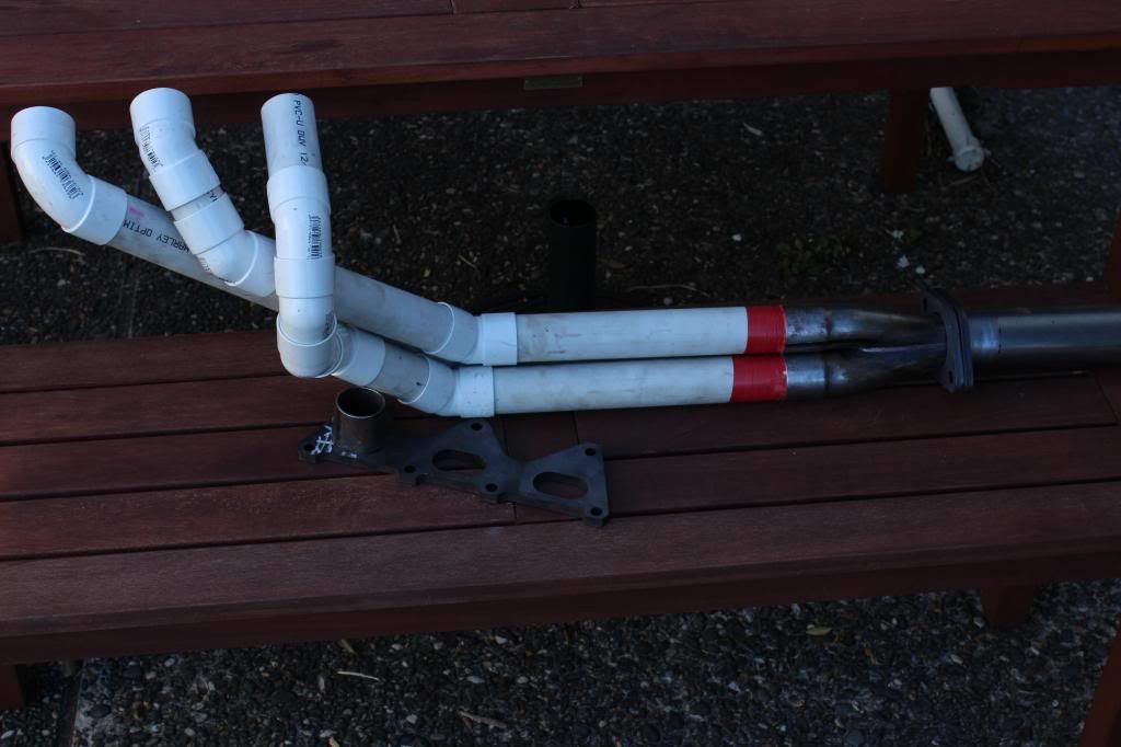
Extractor design: Mild steel material, laser cut flanges port matched, 3 into 1 primaries, custom made venturi style merge collectors, secondaries meeting at a siamese crossover pipe.
Data: 594cc per cylinder, 94mm bore x 85.6 stroke, Exhaust cam specs that come from a GM workshop manual and i can tell there is an error in these and i cant be bothered degreeing my ex cam. all values at 0.150mm lift: Duration 238, opens -229btdc = 69bbdc, closes 9 atdc, centerline 111, overlap 0, cam lift 42.5mm, valve lift 10.8mm, Ecu controlled phasing upto +50 but my ex cam phase map shows +20 across the rev range at wide open throttle . I would love to know the ex valve size anybody have this also has anybody actually degreed an alloytec i only need ex cam specs the error from the GM manual is the degreeing dosnt match the duration FAIL!
Calculations: Primary pipes 1.5"dia x 40" length for 4500rpm 38" for 5000rpm, Collector 6.17" length 2"dia venturi tapered out to 2.25" exit, secondaries 2.25"dia 37" lenght to crossover.
Thats about where im at so far ill probly put flanges on collectors where they get to 2.5" so i can take out the venturi and experiment with length, venturi size and taper for fine tuning. Also another science experiment i would like to try is using a tuning fork and microphone and watching how sound waves travel through each pipe if i make them right all pipes should be in perfect harmony its just a theory because sound is just a pressure wave if i record it and watch it on a pc it will be like a pressure wave scope well see how this goes im not holding my breath for this to work.
And to make things a little easier i have access to a really nice engineering workshop and dyno. You need a really fancy cutter to make the cuts for the merge collector im not even going to try and bother explaining it ill take some pics when i make them and i priced up materials to make them today worked out about $600nz.
Im open to ideas and suggestions so fire away if you have any advice.

Is there any engineers out there (not the welding or fabricating kind) or exhaust gurus that can help with some numbers i think iv got it right but this engine is a nightmare to calculate the ideal length for the pressure wave's due to cam phasing.
Design goals: Its a street car so broad torque curve with peak pressure wave efficiency at 4500rpm-5000rpm in theory about -3 to -5 psi at the exhaust valve.
Extractor design: Mild steel material, laser cut flanges port matched, 3 into 1 primaries, custom made venturi style merge collectors, secondaries meeting at a siamese crossover pipe.
Data: 594cc per cylinder, 94mm bore x 85.6 stroke, Exhaust cam specs that come from a GM workshop manual and i can tell there is an error in these and i cant be bothered degreeing my ex cam. all values at 0.150mm lift: Duration 238, opens -229btdc = 69bbdc, closes 9 atdc, centerline 111, overlap 0, cam lift 42.5mm, valve lift 10.8mm, Ecu controlled phasing upto +50 but my ex cam phase map shows +20 across the rev range at wide open throttle . I would love to know the ex valve size anybody have this also has anybody actually degreed an alloytec i only need ex cam specs the error from the GM manual is the degreeing dosnt match the duration FAIL!
Calculations: Primary pipes 1.5"dia x 40" length for 4500rpm 38" for 5000rpm, Collector 6.17" length 2"dia venturi tapered out to 2.25" exit, secondaries 2.25"dia 37" lenght to crossover.
Thats about where im at so far ill probly put flanges on collectors where they get to 2.5" so i can take out the venturi and experiment with length, venturi size and taper for fine tuning. Also another science experiment i would like to try is using a tuning fork and microphone and watching how sound waves travel through each pipe if i make them right all pipes should be in perfect harmony its just a theory because sound is just a pressure wave if i record it and watch it on a pc it will be like a pressure wave scope well see how this goes im not holding my breath for this to work.
And to make things a little easier i have access to a really nice engineering workshop and dyno. You need a really fancy cutter to make the cuts for the merge collector im not even going to try and bother explaining it ill take some pics when i make them and i priced up materials to make them today worked out about $600nz.
Im open to ideas and suggestions so fire away if you have any advice.
")