Welcome to Just Commodores, a site specifically designed for all people who share the same passion as yourself.
You are using an out of date browser. It may not display this or other websites correctly.
You should upgrade or use an alternative browser.
You should upgrade or use an alternative browser.
markovr
Well-Known Member
- Joined
- Nov 23, 2003
- Messages
- 3,072
- Reaction score
- 252
- Points
- 83
- Age
- 62
- Location
- northside brisbane
- Website
- youtu.be
- Members Ride
- 07vessv 94vr .04vz wgn,93vp wgn,82 vhV6 wgn 88 vn
Dont need any better bcm or cluster just splice into wires already there.
I've got the diagram ...Ill find it.
Try this link..its to street commodores site http://forum.****************.com.au/showthread.php?t=8436153
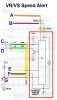
A, circuit# 840, Orange/white stripe.
This goes to fuse # 1,or connector 3 terminal 2 and provides constant power for the unit
B, circuit# 39, Pink/black stripe.
Goes to fuse # 10 , or connector 1 terminal 2 and provides ignition switched 12V+
c, circuit# 1389, Green
Speed output from the speedo to the module.
(connector 2, position 9, behind the cluster)
And: (connector 2, position 8, behind the cluster)
Also shared with the Green wire at the cruise control module
D, circuit# 330, Light Green
Output from the module to the low fuel warning light on the dash.
The module does the prcessing & comparison of the resistance of the fuel sender & triggers the lo-fuel warning light when it beeps.
(connector 1, position 1, behind the cluster)
E, circuit# 209, Yellow
Goes to the yellow wire from the handbrake switch to beep if you drive off with the handbrake on.(connector 1, position 8, behind the cluster)
F, circuit# 151, Black/white stripe
Earth or connector 1 terminal 11
G, circuit# 30, Tan
This ties into the tan wire from the fuel sender that goes to the fuel gauge (connector 1, position 5, behind the cluster)
The diagram is from that site .....thanks for the use of it from the owner.
I've got the diagram ...Ill find it.
Try this link..its to street commodores site http://forum.****************.com.au/showthread.php?t=8436153
A, circuit# 840, Orange/white stripe.
This goes to fuse # 1,or connector 3 terminal 2 and provides constant power for the unit
B, circuit# 39, Pink/black stripe.
Goes to fuse # 10 , or connector 1 terminal 2 and provides ignition switched 12V+
c, circuit# 1389, Green
Speed output from the speedo to the module.
(connector 2, position 9, behind the cluster)
And: (connector 2, position 8, behind the cluster)
Also shared with the Green wire at the cruise control module
D, circuit# 330, Light Green
Output from the module to the low fuel warning light on the dash.
The module does the prcessing & comparison of the resistance of the fuel sender & triggers the lo-fuel warning light when it beeps.
(connector 1, position 1, behind the cluster)
E, circuit# 209, Yellow
Goes to the yellow wire from the handbrake switch to beep if you drive off with the handbrake on.(connector 1, position 8, behind the cluster)
F, circuit# 151, Black/white stripe
Earth or connector 1 terminal 11
G, circuit# 30, Tan
This ties into the tan wire from the fuel sender that goes to the fuel gauge (connector 1, position 5, behind the cluster)
The diagram is from that site .....thanks for the use of it from the owner.
Attachments
Last edited:
Berlina
New Member
- Joined
- Oct 22, 2003
- Messages
- 71
- Reaction score
- 1
- Points
- 0
- Location
- Nowra NSW
- Website
- s64.photobucket.com
- Members Ride
- vz sv6 A5
brendan1414 said:How do i install a speed alert in VR
:bang:
Get Married........:thumbsup:
Sorry about that, I couldnt help myself.......!!!!!!!!!
seabass
New Member
- Joined
- Aug 23, 2005
- Messages
- 122
- Reaction score
- 2
- Points
- 0
- Age
- 36
- Location
- Geelong, VIC
- Members Ride
- VS Berlina 3.8 M5
as simple as putting in a late VR os vs wireing loom from a executive, bout $25n worth. then just buy the controll allt the wireing shud b there, bit of a prick to get the original loom out tho, took me an hour but \shudn't take that long.
email me if ya need any more advice
email me if ya need any more advice
Getthebook
New Member
- Joined
- Mar 11, 2019
- Messages
- 10
- Reaction score
- 5
- Points
- 3
- Age
- 55
- Location
- Melbourne
- Members Ride
- Vs Commodore UTE series 2 3.8 v6
Old post still good info thx very much just for others I found circuit E hand brake on pin 6 ( yellow and matched unit wire) not pin 8 ( blue) ( pin 8 was oil light) on series 2 VS ute. ( maybe a typo online? )Dont need any better bcm or cluster just splice into wires already there.
I've got the diagram ...Ill find it.
Try this link..its to street commodores site http://forum.****************.com.au/showthread.php?t=8436153
A, circuit# 840, Orange/white stripe.
This goes to fuse # 1,or connector 3 terminal 2 and provides constant power for the unit
B, circuit# 39, Pink/black stripe.
Goes to fuse # 10 , or connector 1 terminal 2 and provides ignition switched 12V+
c, circuit# 1389, Green
Speed output from the speedo to the module.
(connector 2, position 9, behind the cluster)
And: (connector 2, position 8, behind the cluster)
Also shared with the Green wire at the cruise control module
D, circuit# 330, Light Green
Output from the module to the low fuel warning light on the dash.
The module does the prcessing & comparison of the resistance of the fuel sender & triggers the lo-fuel warning light when it beeps.
(connector 1, position 1, behind the cluster)
E, circuit# 209, Yellow
Goes to the yellow wire from the handbrake switch to beep if you drive off with the handbrake on.(connector 1, position 8, behind the cluster)
F, circuit# 151, Black/white stripe
Earth or connector 1 terminal 11
G, circuit# 30, Tan
This ties into the tan wire from the fuel sender that goes to the fuel gauge (connector 1, position 5, behind the cluster)
The diagram is from that site .....thanks for the use of it from the owner.
Other colours and pins matched perfect. Looked on other sites with info on pins in cluster plugs and they all point towards pin 6 yellow wire back to VR commodore for handbrake light on . It’s an easy test light check in any case and may save somebody a re-wire . Thx lads