Welcome to Just Commodores, a site specifically designed for all people who share the same passion as yourself.

New Posts Contact us

Just Commodores Forum Community

It takes just a moment to join our fantastic community

Register

[General] HOW TO: Wire up spot lights (VX, VY, VZ and possibly other models)

WazzaV8

New Member
Joined
May 15, 2013
Messages
243
Reaction score
3
Points
0
Location
Esperance
Members Ride
VE SSV Redline
I have been asked a few times as to why wiring up a set of spotties or driving lights can't be done the normal way on a Commodore. The main reason is that the newer style Commodores us what is called "positive switching". Simple terms mean that the switch / line have constant power so wiring up extra lights to work off the high beam in a conventional way will not work.]

I just wired up my VE Commodore the normal way and had no problems, they run off the high beams through a relay and a switch,the switch is under the bonnet, all done the normal way, I use the 5 pin relay so I don't run 2 spotties from 1 pin.
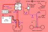
On the 5 pin relay:
30-connect to battery or constant power (wire a fuse in line)
85-connect to earth
86-connect to Hi Beam live wire(red) (wire a switch in line e.g hi bean wire to incab switch then back to relay
87-connect to one spottie
87-connect to other spottie

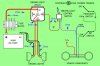
Instead of splicing into the Hibeam wire you can buy a male and female plug compatible to your standard Hibeam plug to globe and make a bridge with a wire from the live (red) to the relay.

For NIGHTMARE...my advice is make your own loom, however with the one supplied I had one recently before I decided to make my own, but from the supplied one you will have 4 wires going to Spot Lights (2xblack and 2x white), you should have three other wires 1.Black to earth 2.Red (with fuse) to battery 3. White(maybe) with switch which has to go to your high beam live wire. This wire will need to go from your hi beam live wire into your car to the switch then another wire from your switch to your relay. To find the hi beam live wire it's either red or you can use a circuit tester, handy cheap tool that is a length of wire with an alligator clip on one end and a housing with a globe on the other end, if a wire is live it comes on. Just test the wires at the connector (where plugs into globe)with hi beams off, then turn hi beam on and test them, the one that has power when hi beams are on is the one you want, circuit testers cost about $5 at Repco, Autobahn etc.

To make your own loom does cost few bucks..$10 for 5 pin relay $10 for wire (but can use what you have already, plus connectors and shrink tubing $15-25.
 
Last edited:

nitemares

New Member
Joined
Nov 11, 2012
Messages
14
Reaction score
2
Points
3
Age
60
Location
Buderim, Queensland
Members Ride
2007 VZ White Crewman ute.
I have just had a look again at the diagram on the first page.

Off to work now....have to love night shifts.....so I have not been able to look around in the engine bay.

But do you propose that the on/off switch that came with the kit be wired across the green and white/b connection on the headlight connector, and that connections 85 and 86 be spliced into that loop as well as per the diagram.

If that is the case....then that is all I have done wrong and now things fit. The exisiting loom provides the power and circuit to the two driving lights. I just need to get the switch side of things into play.

I do hope I am reading this right now.....looks like I need to bridge across the realy and the two headlight connection point.....or not????? Sort of befuddles me.
 

nitemares

New Member
Joined
Nov 11, 2012
Messages
14
Reaction score
2
Points
3
Age
60
Location
Buderim, Queensland
Members Ride
2007 VZ White Crewman ute.
Okay...2 x 14 hour night shifts done and dusted. Thought about things whilst at work.....read some other bits and pieces on the net. Little sleep today and then went to Jaycar and got the attached photo items......roll of auto wire.....5 pin 30amp 12 volt relay......prewired base for this relay...easier to solder then crimp/join for me.....and some heatshrink.

Up and at these bloody driving lights tomorrow....Will wire them in as per the diagram and fingers will be crossed. Wish me luck.
 

Attachments

  • RelayBits01.jpg
    RelayBits01.jpg
    346.8 KB · Views: 1,378

sixes

UTEPILOT
Joined
May 3, 2004
Messages
263
Reaction score
15
Points
18
Location
Somewhere north of Melbourne
Website
www.utepilot.com
Members Ride
VY SS II M6 Ute
Looks good. From what I can gather, you can still use your switch as long as it goes somewhere as stated in the pic. This allows you to flick the lights off if you only want high beam. Having the switch also keeps things legal (check your state laws first).

I have sold my HID spotties and gone for a single 8inch LED light bar (still using the same wiring). Will post a pic when I have it all installed.

Let us know how you go with the wiring.
 

WazzaV8

New Member
Joined
May 15, 2013
Messages
243
Reaction score
3
Points
0
Location
Esperance
Members Ride
VE SSV Redline
thanks heaps this was heaps good. spent the arvo trying to figure out how to wire some spotties up and it was driving me crazy, hopefully after this, i can fix it up tomorrow

That's why I did not include "VE" in the title with this mod.

VE flashes the positive side of the headlights rather than the negative as in previous models.

But that's also the way I wired up the spotties on my VX
 

nitemares

New Member
Joined
Nov 11, 2012
Messages
14
Reaction score
2
Points
3
Age
60
Location
Buderim, Queensland
Members Ride
2007 VZ White Crewman ute.
May the dumb never have spotties.....pick me.

Let us know how you go with the wiring.

Okay got all things happening....soldering heatshrinking and got a big FAIL.

I must be the worlds dumbest vehicle owner.....hard mantle to carry....but somebody has to do it.

Okay, I wired everything as per your diagram.....was left with a thin black earth lead from the old four pin relay. Without this connected to anything I get one spotlight on all the time....regardless of hi or lo beam....and regardless of switch position inside cab. The other one does not come on ever.

I did some looking around and saw that in this diagram (attached with pink background) for positive switching that pin 85 was earthed.....so I spliced into pin 85 and ran that little black lead to an earth bolt/nut. With this on the other spotlight comes on and stays on regardless of hi and lo beam and regardless of switch position. But, when I raise Hi and Lo beam the other light comes on as it should.....half right now.

What I have done:-

1. Remove old relay from vehicle. Undo battery negative terminal.

2. Identify the pin numbers on new relay and match them to the connector and tails.....strip, tin the tails....mark them as well. Double/Triple/Quad check that they are numbered correctly.

3. Solder and heat shrink the new connector to both white leads from the spotlights....to pins 87 and 87a.

4. Solder and heat shrink the pin 30 to the existing power lead with a fuse in the line.....to battery positive post.

This is the interesting bit....and I guarantee where the dumb ass I am made the mistake.

5. Spliced and soldered a new lead from pin 86 (soldered and heat shrink into connector tail) to the green wire at the back of the headlight connector on the right vehicle headlight (the one behind the battery.)

6. Spliced and soldered a red thin lead that goes to the switch in the cab to the bottom white/black wire on the head light block.

7. Soldered and heat shrink the white thin lead that goes to other side of the switch in the cab to lead at base of connector that goes to pin 85.

8. After getting the first result I then did some reading on the NET and found the attached diagrams.....as a result I then returned and spliced soldered and wrapped the little earth lead to the connector lead going to pin 85.

The pink picture is listed as positive switching and the green background is listed as negative switching at this site:-

negative switching lights. How to wire up driving lights???? - Patrol 4x4 - Nissan Patrol Forum

Really lost now.....any ideas at all.....worlds dumbest dude is missing something I do believe.
 

Attachments

  • alternate.jpg
    alternate.jpg
    67.1 KB · Views: 12,948
  • negative switching.jpg
    negative switching.jpg
    69.2 KB · Views: 12,343

nitemares

New Member
Joined
Nov 11, 2012
Messages
14
Reaction score
2
Points
3
Age
60
Location
Buderim, Queensland
Members Ride
2007 VZ White Crewman ute.
Finally we have light.

Whilst trying to fit these things I have flattened the battery. Whilst waiting for the charger to work I found this on the net.

The "Works Every Time" method for car Automotive Driving Light wiring. « Paul’s esoteric meanderings

The text:-

"The "Works Every Time" method for car Automotive Driving Light wiring.

I frequently see wiring diagrams for Driving Lights that just don’t work in many cars.

Toyota nearly always and Nissan often use a what is known as “switched earth” wiring for their headlights. They do this so that each headlight can have it’s own 12v supply and fuse, meaning in the event of a problem, you only lose one light.

In a switched earth headlight, assuming you are using a H4 bulb with 3 pins (very common) the power is switched twice. +12V is fed through a relay or switch to the common pin, and then either one of the other pins (one for High, one for Low) is alternately connected to ground through another relay or switch. If you go looking for +12V to power your driving lights or their relay in this system, you wont find it easily.

A far easier method is to always wire the trigger for your relay ACROSS the high beam bulb circuit, instead of from +12v to ground. This means that regardless of the vehicle wiring, positive or negative switched, the driving light wiring is the same.

There are several other benefits to wiring in this manner.

a) It works with either positive of negative switched headlights

b) It avoids problems with the relay not dropping out. The high beam indicator inside the car can trickle enough power through to not let the driving lights drop out. It takes about 8-9V to trigger a 12V relay, but only about 4V to hold it in.

c) It avoids problems with the relay not dropping out due to a poor contact on the headlight connection. This common fault can setup a circuit through the other filaments and cause enough voltage to be present on the high beam filament to hold the relay open. This voltage is far less across the filament than in relation to ground.

So how do you wire it?

It’s easy really. I have gone with text, as many people have trouble with electrical diagrams.

Power CCT (Heavy wire)
Battery – Fuse – Relay (Pin 87) – Relay (Pin 30) – Driving Lights – Chassis (Ground)

Switch CCT (Light wire)
Headlight Common Pin – Switch – Relay (Pin 85) – Relay (Pin 86) – Headlight High Beam Pin

Simply tap into the headlight wires / pins with vampire taps.

Presto – I guarantee it will work.

If you don’t have H4 bulbs, even easier, simply go straight across your high beam bulb wires for the trigger."


The pics that refer are attached as well. I did not understand why he has the relay going backwards.......power to pin 87 and then both spotlights wired to pin 30.....my five pin relay now has one connection free. But it actually bloody works. Phew. I believe that Vampire Taps are scothlok or similar....which I used.

image6.pngimage7.png
 
Last edited:

Nut Kracker

Donating Member
Joined
Oct 18, 2012
Messages
4,760
Reaction score
149
Points
63
Age
64
Location
Echuca Vic.
Members Ride
VT SS 304ci (195i)
I have been following this thread for a while and can't believe why something so simple as wiring driving lights
has become so complicated.

Get rid of the relay and wiring that came with it. It's crap, too confusing and not needed.
Use your own relay and wiring.

I've done it the following way on a lot of 4x4's and never had any trouble.

Using a four pin 30 amp relay.....
Pin 85... to switch and then to light green wire (high beam earth wire VT/VZ) This wire is the switching side of your standard high beam lights.
Pins 86 and 30.... to Battery +12volts.
Pin 87... to + side of driving lights (wired in parallel)
Connect earth wires of driving lights to ground.

All that is happening is when the high beam is activated,
it turns on the relay (through pins 85 and 86), allowing power to flow through the connections (pins 30 and 87) to the driving lights.
Simple....

It doesn't mater which way pins 85 and 86 are wired, they are not polarity sensitive.
Just as long as one is + and the other one is -.
You can also put the switch on either pin 85 or 86, it doesn't matter.

If your standard high beam lights are POSITIVELY switched,
connect pin 86 to EARTH and leave the rest as described.


And all this is just from memory.

Using a 5 pin relay and wiring each light to pins 87 and 87a will not work, as when the relay is activated,
pins 87 and 87a are not joined as one connection.
I think that when the relay is off, pins 87a and 30 are connected and when the relay is activated,
pins 30 and 87 are connected. Or vice versa.
 
Last edited:

Ghost

Donating Member
Joined
Sep 29, 2011
Messages
1,238
Reaction score
4
Points
38
Age
38
Location
Junee New South Wales
Members Ride
Vs Commodore berlina Sedan 1996
Good luck registering it with it wired like that by law the driving lights have to be wired to an independent switch if there is no switch to disable them say hello to a defect notice in nsw and also pick up a pamphlet from the rms about mis understood road rules because spot lights can't be used while driving
 
Top