litch
New Member
- Joined
- Apr 6, 2015
- Messages
- 12
- Reaction score
- 0
- Points
- 1
- Location
- Australia
- Members Ride
- VE Series II SSV Redline
Greetings all.
I'll be detailing my system build in my (recently purchased) 2012 SSV Redline Sportswagon. Hopefully it helps someone along the way.
TL;DR - If you have a VE Sportswagon you can find pictures, schematics and box designs here.
The Plan
At the time of this thread's creation, I've built and installed the custom sub box, power wiring for 1 battery and the LOM for testing, but I'll continue to update as the work progresses to the final stage of installation.
The Sub Box - Design/Build
My main aim when installing this system was to balance the following:
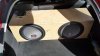
So with boot space and SQ in mind - I decided to sacrifice some SPL and went for a sealed enclosure firstly because a sealed box is inherently smaller than a ported one and secondly the response curve is a little smoother (but drops off sharper down low). Now the manufacturer wants 2cuft NET (Meaning it's 2cuft inside the box, minus the volume the sub takes up as well; ie. 2cuft of actual air) - and if you own a Sportswagon you'll know the boot isn't exactly teaming with space, there's only about 330mm from the rear of the back seats to where the inside panels narrow significantly - also there's about 390mm from the floor to where the horizontal "boot cover" bar comes across immediately behind the top of the back seats, and within that whole area there's about 1220mm of width to play with.
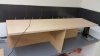
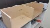
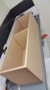
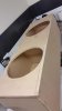
With all that in mind, I set to work in Excel and spun up a template where I could tweak values to get the right size (also taking into account the subs are 390mm high) and once I got it close enough to 2cuft - I took the final measurements down to Mitre10 and told them to cut it using their wall-saw (much more accurate than my circular saw abilities ). The box was cut to-the-millimetre using 18mm MDF and cost under $40 including 100 x 8G/45mm wood screws and a tube of liquid nails. Assembly took a couple of hours (including dry time) - but the result was dead square.
Photos in ZIP:
The Sub Box - Fit out
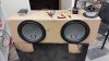
With the box built and just sitting there (waiting for the carpet and other power parts I ordered to be delivered) - I grew impatient and decided to throw something together with what I had as a temporary solution (at least get to hear what it sounded like).
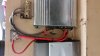
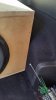
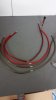
The amps I had previously - an decade-old but reliable power-house monoblock: An Orion 2500D and a crappy Precision Power 600W 4ch (to be replaced in due time) were ready to mount, so I dug through the bottom of my "old car audio installs" box for some power distro and 4AWG and set to work. Since these subs could take the best part of the 2500W from the monoblock, I ran 8AWG in a DVC-parallel+Sub-Parallel configuration to leverage that 1Ohm power level (4 Ohm voice coils in parallel = 2 Ohm per sub, then both subs in parallel = 1 Ohm final).
HINT: Ensure you amp is 1Ohm stable before you go ahead and wire it up that way, else you'll risk damaging it.
Photos in ZIP:
The Sub Box - Install
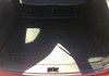
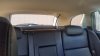
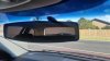
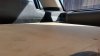
I knew the box had to be installed from the back seats and pushed into place, the Sportswagon's boot opening is smaller than the width of the box (and thus, so it most of the boot from the tailgate to the area just before the back seats) - the one thing I didn't count on was the damn back seat latch pegs; 3 inches of hardened steel protruding out from each side where the back seats lock into place. (Hint: Multigrips took care of them). After that I was able to finally see how everything fit - and it was like a f@#%ing glove.
Photos in ZIP:
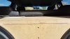
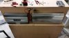
As you can see in the photos, the box fits snug up against the back seat while the seat's vertical angle allows the amps and wiring to remain hidden. The box's height still allows for the boot cover bar to be installed, and it's depth fits it snug up against the narrowing side panels - keeping it stationary.
LOM and wire looms
A Line Out Module, Line interface module, Line OEM module or however many other names it has essentially takes the 40-60 Watt audio channel designed to power speakers directly and converts it to line-out levels (low power audio designed to drive the RCA inputs to amps). It's the effective, low cost solution that doesn't require you spending a grand to replace the whole dash with after-market audio gear. The Soundstream iCQ4 unit I have is what you would call "middle-shelf" quality and does the job quite well, but for "full-on" SQ installs, you would look a few shelves higher so-to-speak.
So, in an ideal LOM install - the unit would be placed at or near the audio source (Holden IQ) - like under/in the glovebox or behind the kick panel. In this case I just threw it on top of the sub box for the sake of and easy place to be tuned (to be removed and properly installed when I receive all the other gear). I tapped the rear door speakers via the wire loom under the kick-step of the driver and passenger front doors. There's an absolute mess of wires in there with the rear-speaker colour codes *not* being unique.
HINT: The speaker wire-pairs (+ and -) are twisted together, as far as I could see - no other wires were in that loom.
Colour codes:
I simply cut them, soldered on a couple of 16AWG speaker wire, taped it up and ran it back to the LOM (feed from IQ) and the 4ch (return to speaker). Then set the LOM to 2ch mode - taking the 2ch from the rear speakers and duplicating it into 4ch output; 2ch for the 4ch amp which will run the rear speakers for the time being and 2ch for the monoblock.
Power
The VE has the battery in the boot, left side panel just in from the tailgate. Convenient? Yes, but at what cost... The alternator in the SSV is 140A - significant for a sedan, but it's got a LOT of electrics and I'm unsure of how big the alternator->battery wire is. I can see about a 4AWG from the battery going towards the engine bay (which I'm hoping is the alternator feed) but there's also a small ~10AWG cable bolted to the side of the battery terminal with "ALT" stamped next to it - totally insufficient for my level of power requirements if that's the case; further investigation necessary (TBC)...
HINT: To run the power from the battery, there are Torx screws along the top of the side panel that allows its removal where you can then easily access the inside quarter panel (and the battery there-in) all the way to the rear seat mounts. I'll be detailing this when I install the other battery w/photos etc..
Initial tests
Wow, sounds really good. Very loud, punchy and hits every note, though starts to struggle below 50Hz; a bit of baffle may help that.
HINT: "Baffle" or "Dampening" (that soft, white fluffy material somewhere between insulation bats and cotton wool) attenuates the sound waves inside the box. When your sub fails to drop low it can be because the sounds waves are bouncing off the back of the box and slapping back into the cone at the same time it's going back for another pressure wave (that's called a standing wave or resonance). Baffle reduces this negative feedback on the woofer cone - essentially emulating a larger enclosure and smoothing out the resonance curve. The basic rule of thumb is that a larger enclosure will hit deeper notes (to a point). If you find you're not hitting low as well as you'd like, adding a few inches of baffle at the rear of the box can help substantially (at the cost of taking some of that "punchyness" away). You'll need to see how much you need by trial and error, too much and you'll start to dig in to performance, too little and you won't notice anything. Note that low powered systems (ie ~300W subs) will suffer more performance loss when using baffle than higher powered systems of the same physical size.
The stock speakers in the rear (now powered by the amp) sound twice as good as the front doors - clearer, better response up each end of the spectrum and it's now made painfully apparent that the front door and centre speaker are under-performing.
Coming up...
Enough Dynamat to cover a small stadium, some better power distribution and some HQ speaker wire are all en-route, but the JBLs are still on back-order from the USA.
The next update will be once the JBLs come in, and I'll detail:
Also I'll try get some videos to accompany the install photos.
-Litch
[EDIT] Site won't let me upload the Excel doc I built, so I've included a screenshot and I'll email the original on request.
I'll be detailing my system build in my (recently purchased) 2012 SSV Redline Sportswagon. Hopefully it helps someone along the way.
TL;DR - If you have a VE Sportswagon you can find pictures, schematics and box designs here.
The Plan
- 2 x MTX T8515-44 15" Subs
- 2500W monoblock / 600W 4ch
- JBL P662 6.5" Coax (rear door)
- JBL GTO 609C 6" Splits (Front door)
- Sourced using a Soundstream iCQ4 Line-Out Module (which will convert the existing Holden IQ speaker outputs into line-out RCAs)
- Dual battery (System will be in the 2,000-3,000W range)
At the time of this thread's creation, I've built and installed the custom sub box, power wiring for 1 battery and the LOM for testing, but I'll continue to update as the work progresses to the final stage of installation.
The Sub Box - Design/Build
My main aim when installing this system was to balance the following:
- SPL (I like to ground'n'pound)
- SQ (But I should at least make an effort in retaining some SQ)
- Boot room (And I don't want to take up the whole boot)
So with boot space and SQ in mind - I decided to sacrifice some SPL and went for a sealed enclosure firstly because a sealed box is inherently smaller than a ported one and secondly the response curve is a little smoother (but drops off sharper down low). Now the manufacturer wants 2cuft NET (Meaning it's 2cuft inside the box, minus the volume the sub takes up as well; ie. 2cuft of actual air) - and if you own a Sportswagon you'll know the boot isn't exactly teaming with space, there's only about 330mm from the rear of the back seats to where the inside panels narrow significantly - also there's about 390mm from the floor to where the horizontal "boot cover" bar comes across immediately behind the top of the back seats, and within that whole area there's about 1220mm of width to play with.
With all that in mind, I set to work in Excel and spun up a template where I could tweak values to get the right size (also taking into account the subs are 390mm high) and once I got it close enough to 2cuft - I took the final measurements down to Mitre10 and told them to cut it using their wall-saw (much more accurate than my circular saw abilities
). The box was cut to-the-millimetre using 18mm MDF and cost under $40 including 100 x 8G/45mm wood screws and a tube of liquid nails. Assembly took a couple of hours (including dry time) - but the result was dead square.Photos in ZIP:
- Box Build 1-4
The Sub Box - Fit out
With the box built and just sitting there (waiting for the carpet and other power parts I ordered to be delivered) - I grew impatient and decided to throw something together with what I had as a temporary solution (at least get to hear what it sounded like).
The amps I had previously - an decade-old but reliable power-house monoblock: An Orion 2500D and a crappy Precision Power 600W 4ch (to be replaced in due time) were ready to mount, so I dug through the bottom of my "old car audio installs" box for some power distro and 4AWG and set to work. Since these subs could take the best part of the 2500W from the monoblock, I ran 8AWG in a DVC-parallel+Sub-Parallel configuration to leverage that 1Ohm power level (4 Ohm voice coils in parallel = 2 Ohm per sub, then both subs in parallel = 1 Ohm final).
HINT: Ensure you amp is 1Ohm stable before you go ahead and wire it up that way, else you'll risk damaging it.
Photos in ZIP:
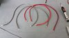
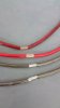
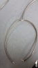
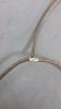
- Sub Wires 1-5 - shows how to properly cable up the subs by mid-joining DVC cross connects.
- Temp Build Back / Temp Build Front - Showing the temporary throw-together.
The Sub Box - Install
I knew the box had to be installed from the back seats and pushed into place, the Sportswagon's boot opening is smaller than the width of the box (and thus, so it most of the boot from the tailgate to the area just before the back seats) - the one thing I didn't count on was the damn back seat latch pegs; 3 inches of hardened steel protruding out from each side where the back seats lock into place. (Hint: Multigrips took care of them). After that I was able to finally see how everything fit - and it was like a f@#%ing glove.
Photos in ZIP:
- All "Box Fit" photos...
As you can see in the photos, the box fits snug up against the back seat while the seat's vertical angle allows the amps and wiring to remain hidden. The box's height still allows for the boot cover bar to be installed, and it's depth fits it snug up against the narrowing side panels - keeping it stationary.
LOM and wire looms
A Line Out Module, Line interface module, Line OEM module or however many other names it has essentially takes the 40-60 Watt audio channel designed to power speakers directly and converts it to line-out levels (low power audio designed to drive the RCA inputs to amps). It's the effective, low cost solution that doesn't require you spending a grand to replace the whole dash with after-market audio gear. The Soundstream iCQ4 unit I have is what you would call "middle-shelf" quality and does the job quite well, but for "full-on" SQ installs, you would look a few shelves higher so-to-speak.
So, in an ideal LOM install - the unit would be placed at or near the audio source (Holden IQ) - like under/in the glovebox or behind the kick panel. In this case I just threw it on top of the sub box for the sake of and easy place to be tuned (to be removed and properly installed when I receive all the other gear). I tapped the rear door speakers via the wire loom under the kick-step of the driver and passenger front doors. There's an absolute mess of wires in there with the rear-speaker colour codes *not* being unique.
HINT: The speaker wire-pairs (+ and -) are twisted together, as far as I could see - no other wires were in that loom.
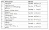
Colour codes:
- For rear-left, it's Brown(+) and Yellow w/Red stripe(-)
- For rear-right, it's Dark Blue(+) and Light Blue(-)
- For front-left, it's Brown(+) and Grey(-)
- For front-right, it's Light Green(+) and Dark Green(-)
I simply cut them, soldered on a couple of 16AWG speaker wire, taped it up and ran it back to the LOM (feed from IQ) and the 4ch (return to speaker). Then set the LOM to 2ch mode - taking the 2ch from the rear speakers and duplicating it into 4ch output; 2ch for the 4ch amp which will run the rear speakers for the time being and 2ch for the monoblock.
Power
The VE has the battery in the boot, left side panel just in from the tailgate. Convenient? Yes, but at what cost... The alternator in the SSV is 140A - significant for a sedan, but it's got a LOT of electrics and I'm unsure of how big the alternator->battery wire is. I can see about a 4AWG from the battery going towards the engine bay (which I'm hoping is the alternator feed) but there's also a small ~10AWG cable bolted to the side of the battery terminal with "ALT" stamped next to it - totally insufficient for my level of power requirements if that's the case; further investigation necessary (TBC)...
HINT: To run the power from the battery, there are Torx screws along the top of the side panel that allows its removal where you can then easily access the inside quarter panel (and the battery there-in) all the way to the rear seat mounts. I'll be detailing this when I install the other battery w/photos etc..
Initial tests
Wow, sounds really good. Very loud, punchy and hits every note, though starts to struggle below 50Hz; a bit of baffle may help that.
HINT: "Baffle" or "Dampening" (that soft, white fluffy material somewhere between insulation bats and cotton wool) attenuates the sound waves inside the box. When your sub fails to drop low it can be because the sounds waves are bouncing off the back of the box and slapping back into the cone at the same time it's going back for another pressure wave (that's called a standing wave or resonance). Baffle reduces this negative feedback on the woofer cone - essentially emulating a larger enclosure and smoothing out the resonance curve. The basic rule of thumb is that a larger enclosure will hit deeper notes (to a point). If you find you're not hitting low as well as you'd like, adding a few inches of baffle at the rear of the box can help substantially (at the cost of taking some of that "punchyness" away). You'll need to see how much you need by trial and error, too much and you'll start to dig in to performance, too little and you won't notice anything. Note that low powered systems (ie ~300W subs) will suffer more performance loss when using baffle than higher powered systems of the same physical size.
The stock speakers in the rear (now powered by the amp) sound twice as good as the front doors - clearer, better response up each end of the spectrum and it's now made painfully apparent that the front door and centre speaker are under-performing.
Coming up...
Enough Dynamat to cover a small stadium, some better power distribution and some HQ speaker wire are all en-route, but the JBLs are still on back-order from the USA.
The next update will be once the JBLs come in, and I'll detail:
- HOWTO: Door speaker/speaker wire upgrade
- Proper LOM installation, tapping into the Holden IQ audio plugs at the dash
- Power distribution, alternator feed, second battery install
- How it looks with a carpeted box
Also I'll try get some videos to accompany the install photos.
-Litch
[EDIT] Site won't let me upload the Excel doc I built, so I've included a screenshot and I'll email the original on request.
Attachments
-
 Amp Power.jpg87.2 KB · Views: 525
 -
 Boot.jpg107.9 KB · Views: 329
 -
 Box Build 1.jpg61.8 KB · Views: 485
 -
 Box Build 2.jpg67.5 KB · Views: 449
 -
 Box Build 3.jpg37.1 KB · Views: 358
 -
 Box Build 4.jpg37.8 KB · Views: 327
 -
 Box Fit - Driver Side.jpg44 KB · Views: 385
 -
 Box Fit - Over Back Seat View.jpg115.7 KB · Views: 529
 -
 Box Fit - Overview.jpg163.6 KB · Views: 407
 -
 Box Fit - Passenger Side.jpg54.1 KB · Views: 305
 -
 Box Fit - Rear View.jpg182.3 KB · Views: 391
 -
 Box Fit - Top vs Boot Cover Mount.jpg141 KB · Views: 503
 -
 Box Fit - Top vs Rear Seats.jpg207.9 KB · Views: 374
 -
 Sub Wires 1.jpg130.4 KB · Views: 434
 -
 Sub Wires 2.jpg32.3 KB · Views: 379
 -
 Sub Wires 3.jpg34.7 KB · Views: 409
 -
 Sub Wires 4.jpg30.1 KB · Views: 337
 -
 Sub Wires 5.jpg28.4 KB · Views: 356
 -
 Temp Build Back.jpg145.1 KB · Views: 336
 -
 Temp Build Front.jpg200.4 KB · Views: 413
 -
 VE Audio.jpg59.5 KB · Views: 367
 -
 Wagz.jpg151.3 KB · Views: 334
 -
 SubCalc - SSV v1.jpg53.3 KB · Views: 344
Last edited: