Welcome to Just Commodores, a site specifically designed for all people who share the same passion as yourself.

New Posts Contact us

Just Commodores Forum Community

It takes just a moment to join our fantastic community

Register

VS Fuel Sender Into A 94 VR??

Seb.v

New Member
Joined
Aug 20, 2023
Messages
8
Reaction score
0
Points
1
Age
19
Location
Victoria
Members Ride
Vr acclaim, Buick s2
Just wanna find out if i could get a vs fuel sender unit and cut the plugs off the vs and re solder the wires on the VR and try use the vs plugs and sender going into the VR tank. Just that i cant find a VR fuel sender unit but a vs one is a every wrecker. Can someone let me know if they've done this before or if it would work. Cheers
 

BlackVXGTS

Well-Known Member
Joined
Aug 14, 2004
Messages
5,504
Reaction score
2,517
Points
113
Location
Melbourne, SE
Members Ride
GEN-F2 GTS A6, VS Clubsport 185 A4
The electrical connection system is slightly different between the VR/VS, but you could certainly solder the VR wires onto the VS plug. There are only two wires involved from the VR side but I'm not sure about the VS side.

1705215091992.png
VR
1705215399358.png
VS
 

Seb.v

New Member
Joined
Aug 20, 2023
Messages
8
Reaction score
0
Points
1
Age
19
Location
Victoria
Members Ride
Vr acclaim, Buick s2
see what your saying, but there is only one plug on the vs sender. how would i go about putting the vr plugs onto the vs sender unit?
 

07GTS

Well-Known Member
Joined
Sep 8, 2013
Messages
5,002
Reaction score
6,680
Points
113
Location
Australia
Members Ride
VEGTS BUILT BLOWN E85
vs plug is 4 wires, 2 for sender and 2 for pump, just workout whats what on the vr and connect them up to same on the vs
 

BlackVXGTS

Well-Known Member
Joined
Aug 14, 2004
Messages
5,504
Reaction score
2,517
Points
113
Location
Melbourne, SE
Members Ride
GEN-F2 GTS A6, VS Clubsport 185 A4
This has turned out to be a bit confusing. The VR diagram in my post #2 shows one connector to the body of the sender unit which which contains the (C) level sender earth and the (D) level sender signal. The other loose connector shows white and red wires but both are labelled as fuel pump on. Presumably the red wire is the (A) fuel pump power wire. Don't know about the white wire.

Searching around, I found the information and VS diagram below, as well as the link for a new connector that you could plug the VR wires into to attach them to the VS sender.

(A) thick purple is fuel pump power
(B) thick black is earth
(C) thin black is level sender earth
(D) thin yellow or tan is level sender signal

1705309683386.png


07GTS

Well-Known Member
Joined
Sep 8, 2013
Messages
5,002
Reaction score
6,680
Points
113
Location
Australia
Members Ride
VEGTS BUILT BLOWN E85
This has turned out to be a bit confusing. The VR diagram in my post #2 shows one connector to the body of the sender unit which which contains the (C) level sender earth and the (D) level sender signal. The other loose connector shows white and red wires but both are labelled as fuel pump on. Presumably the red wire is the (A) fuel pump power wire. Don't know about the white wire.

Searching around, I found the information and VS diagram below, as well as the link for a new connector that you could plug the VR wires into to attach them to the VS sender.

(A) thick purple is fuel pump power
(B) thick black is earth
(C) thin black is level sender earth
(D) thin yellow or tan is level sender signal

View attachment 262886
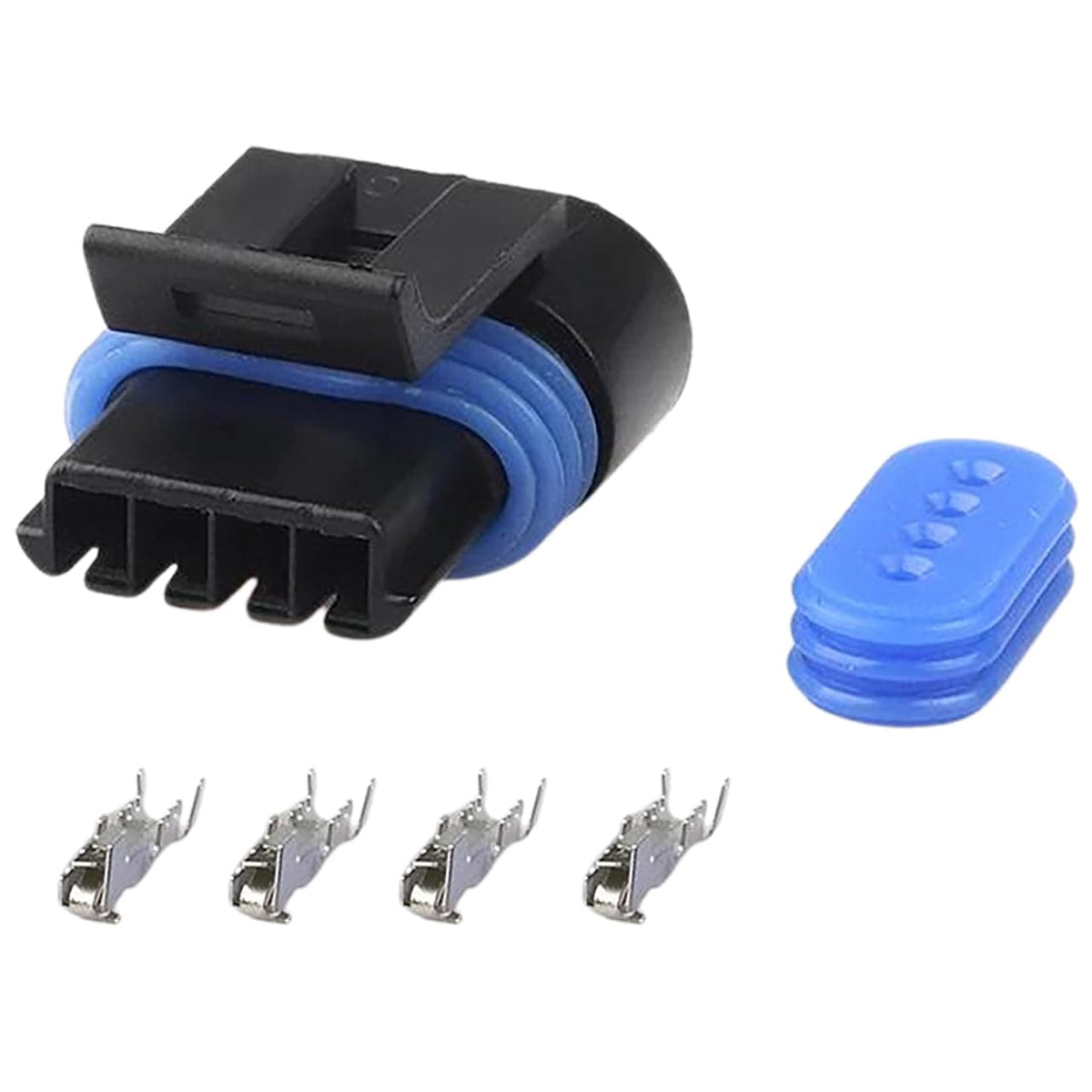
just have to swap ur terminals, the middle two are for the sender B and C, the outside two are for the pump A and D, black in both being the earths, they are both above earth so wont get interference from body earths
 
Top