Level 3 Into VP's
THIS IS THE GUIDE TO INSTALLING LEVEL 3 INTO VP
Parts Needed:-
1 level 3 cluster from either VN-VP-VQ (recommend VP)
1 Trip computer switchblock (left hand side) from a VP calais/berlina LX - VQ staesman series 2 (indentifiable by it being black and having demister dome and hazard on it)
1 Left-hand switchblock from a vp exec/berlina (basic one with only dome, demist & hazard) I recommend using another than the one you have already in your car but if you feel confident than use it.
1 4th connector plug (if you are removing from wreck try to take much wire as possible
1 Plug from level 3 switchblock(one with trip computer buttons as above try to take as much wire as you can)
You will also need things like soldering iron, solder, tape, heat shrink, drill with 11mm drill bit & 4-5mm bit, Small die grinder and/or small file. You will also need wire a fair bit, i'd buy atleast 5m really depends on much extending of you have to do
Installation time is approx. 4 hours but you can do it in stages.
Abbreviations-
SB- Switchblock
PCB- Printer circuit board
First things First, I and the fellow members of JC offer advice and guides on doing this we accept no responsiblity for any damaged caused by following our guides or advice. Everything is done at your own risk!
Now the How To->
Get yourself a copy of the diagrams found in this thread, i found printing them out in colour to be helpful. Remove your Level 1/2 cluster and lay it side by side with your level3. COMPARE the connector layouts on the back of each and copy out the the label. THIS IS ONE OF THE MOST IMPORTANT STEPS AS THE DIAGRAMS ARE NOT THE SAME DUE SOME MODELS/CLUSTER HAVING DIFFERENT WIRING. You will note that some wire are in different location and will need to be moved, Check engine and press remote is a good example.
Ok now use the diagrams and the connector to wire up your level 3 cluster. The yellow & black wire goes to the same colour wire located on your ecu plug (smaller of the 2 i beleive but don't quote me) This part of the install can be quite fiddly you may have to extend a few wires and such. Make sure you solder and insulate all joins. Me being lazy found it easier to "tap into" certain wires by melting plastic with a lighter and soldering then covering with tape. Cutting, soldering and using heatshrink would be better way to go about it.
TIP to remove wires from connectors i used a skewer and push into the middle of the metal tang(be sure to remove the yellow tags that stop them coming out)
MODDING YOUR SWITCHBLOCK
So get your 2 switchblocks and pull them apart.
(TIP wiper boards can be a pain to get off most times i think i'm going to break them. There's a small ball bearing and spring in the wiper switch make sure you dont lose them as they are what make it click when you turn it on and change speeds.)
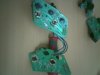
WE will start with the black plastic out shell. What you need to do is pull out the dome and demister parts from both and swap them over. You will notice the level 1 SB has spingy type buttons these need to go into the level 3 SB. This can be a pain due to it hard to get them clear plastic things back together and working smoothly. refer to picture 6
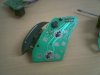
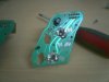
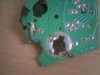
Now the circuit boards or PCB as i will refer to them. Lay them side by side and compare them (picture1) . You will see how the demsiter and dome are different, level 1 uses switches and level 3 are printed on the board. So what we are going to do is remove the switches from the level 1 PCB and put them onto the level 3 PCB. Remove the switches from the level1 PCB 9wire need to be desoldered from board) and you will see the holes required to be made into the level3 PCB. This is tricky you must drill over where the switches will be without damaging the rest of the board, you must also make the grovves at each end of the holeso the switch will fit in. Use a small drill bit to start, The hole is about 11-12mm 12 might be a little too big. So when your done you should have holes similar to the ones in picture 2 but better than my 1st attempt
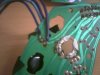
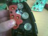
So this is the cunning part of my whole conversion. We are going to extend the wire on the back of both switches (dome and demister) then solder them back onto the level 1 PCB. So they will work the same but will be located on the level3 switchblock. I made a case to keep my level1 PCB so it doesnt get damaged. The reason we keep this is because the functions for the intewrior light delay and demister are done using this board whereas on the level 3 its controlled by a BCM. So that done you should have something that looks like the one in pictures 4,5,7
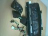
Now the plug in your car which plug into the top of your SB will go to the level 1 board. Now using the one you got for the level 3 extend the 4 wires that go to the 4th connector and solder. (make sure you have enough to reach across). 2 wires (blue and purple on mine) which are on the left side and vertically alinged will not be needed. But the other 3 (2x black and brown &white on mine) need to be tapped in and soldered to the respective locations on the plug that is in your car. So basically what you end up in essence is a piggyback system. (picture 32 is all my peices together)
Now when you reassemble you must use your level 1 wiper board (picture 3) otherwise it will burn out your board and wipers won't work. Now you can reassemble and test assembiling can be frustrating as the switches can get in the way of some things. I had to file down the corner of the demister switch as it was in the way.
Hopefully everything turned out good for you. I have included pictures to help and if you want help post here and i will do my best to get back with a respone.
NOTE IF PEOPLE OUT THERE ARE GOING TO RIP-OFF WHAT I WROTE AND HAVE DONE TO HELP PEOPLE PLEASE GIVE CREDIT TO PEOPLE WHO DID THE HARD YARDS.
My thanks to Markovr, holdendanman, stocky and hozy for helping me with this install.