Grimes
Well-Known Member
- Joined
- May 7, 2020
- Messages
- 410
- Reaction score
- 275
- Points
- 63
- Location
- NSW
- Members Ride
- VS Commodore Series II Ute
Just posting this for information after running into a few issues and working them out. There are a lot of older threads about speedo correctors and where to wire them, but not many I could find on the current Jaycar offering or Dakota unit sold here in Australia by Marks 4WD.
Credit to noisey90 for his post on wiring one of these Dakota units in posted in February. This post just adds some context and detail which might be helpful for someone out there.
First things first, the current offering from Jaycar, the Digitech AA-0376 corrector wouldn’t work at all for me. I tried replacing the unit (which Jaycar were happy to do) innumerable set-up configurations, but it simply would not calibrate. I even tried wiring in my own step-up/step-down resistors to no avail. Save yourself the time and give it a miss. I suspect it’s because it can’t process the sine wave coming from the speed sensor on my Getrag, unlike the square pulse hall effect sensors on T5’s.
The Dakota SBI-100BT sold by Marks 4WD works.
My drive is a VS Getrag 5 speed Ute. As others have suggested I intercepted the violet/white cable between the ECU and dash by cutting the cables above the passenger footwell kick panel.
I extended the speedo cable input/output across to the driver side through the dash so I could mount the corrector unit close to the fuse panel.
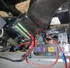
As noisey90 posted earlier this year, wiring in is power to the POWER terminal, GROUND to earth, speedo input to INPUT and speedo output to the dash, OUT2.
I used a fuse jumper plugged into Fuse 10 as shown below for the power source. The corrector unit zip ties neatly to the a/c vent too.
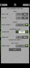
Download the app they give a link to, turn the ignition on and work through the corrections to get the ratio you need. Works a treat.
Hope this helps.

Credit to noisey90 for his post on wiring one of these Dakota units in posted in February. This post just adds some context and detail which might be helpful for someone out there.
First things first, the current offering from Jaycar, the Digitech AA-0376 corrector wouldn’t work at all for me. I tried replacing the unit (which Jaycar were happy to do) innumerable set-up configurations, but it simply would not calibrate. I even tried wiring in my own step-up/step-down resistors to no avail. Save yourself the time and give it a miss. I suspect it’s because it can’t process the sine wave coming from the speed sensor on my Getrag, unlike the square pulse hall effect sensors on T5’s.
The Dakota SBI-100BT sold by Marks 4WD works.
My drive is a VS Getrag 5 speed Ute. As others have suggested I intercepted the violet/white cable between the ECU and dash by cutting the cables above the passenger footwell kick panel.
I extended the speedo cable input/output across to the driver side through the dash so I could mount the corrector unit close to the fuse panel.
As noisey90 posted earlier this year, wiring in is power to the POWER terminal, GROUND to earth, speedo input to INPUT and speedo output to the dash, OUT2.
I used a fuse jumper plugged into Fuse 10 as shown below for the power source. The corrector unit zip ties neatly to the a/c vent too.
Download the app they give a link to, turn the ignition on and work through the corrections to get the ratio you need. Works a treat.
Hope this helps.