- Joined
- Apr 15, 2006
- Messages
- 22,631
- Reaction score
- 20,520
- Points
- 113
- Location
- Sth Auck, NZ
- Members Ride
- HSV VS Senator, VX Calais II L67
This topic has come up in a few threads lately so i though i'd do a how to.
you need:
1 x switch
1 x wire, .5mm2 will be sufficient in size, couple of meters depending on where you locate the switch.
1 x heatshrink (substitute electrical tape if not avail)
basic hand tools: wire cutters, wire stripper, soldering iron etc.
method
1. disconnect the battery negative terminal
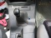
2.first you need to decide where you are going to mount your switch, i've mounted mine next to the gear stick (pic 1)
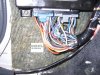
3. remove the passenger side kick panel and locate the wire for the thermo fan relay that comes from the ecu (pic 2), it's a blue wire with a white trace, i suggest unwrapping the wiring loom a little to give yourself more wire to work with
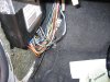
4. you need to splice your bypass switch wire to this blue/white wire(pic 3). there are a couple of ways to do this but i suggest that the best way to do this is to solder it as it's a low current circuit and we need a good connection. i cut the wire and stripped each back about 8mm, then i stripped the bypass wire about 20mm. tin each stripped end slip the heatshrink over one of the wires. i then soldered the bypass wire and wire coming from the loom together and then soldered the wire coming from the ecu to that. then it's a matter of slipping the heatshrink down over the joint and applying some heat. if you don't have heatshrink available then i suggest that you don't cut the blue/white wire, just carefully strip some of the insulation off and solder your bypass wire there, then insulate with electrical tape.
5. pull your wire to your choosen location for your switch, mount and wire the switch.
6. then you need to connect the second side of the switch to an earth point. one possibility is the use the earth side of the sig lighter. i choose to use a screw mounting a panel to the chassis near the ecu(you need to make sure that it's a good earth point).
7. cleanup and secure all the new wiring, re-wrap the wiring loom if you unwrapped it etc.
8. re-connect the battery negative terminal and test, you should be able to turn the key to the 'on' position and be able to switch the thermo fan on with the bypass switch. run engine up to temp to make sure the ecu is still switching thermo fan on.
if your really keen then you can also mount an LED somewhere and wire in series with the new switch, that way you will also have an indicator to tell you that you have the bypass switch on.
there is also a basic wiring diagram attached.
Edit: I've attached the wiring diagram for the VT V6 Commodore. From VT onward the PCM switched the high speed thermo fan and the low speed thermofan is switched from the BCM. For best effect this mod should be wired into the high speed relay fan using the Blue wire with white trace (BLU/W) from pin F6 on the PCM (as per the wiring diagram 5a bellow).
happy wiring:thumbsup:
you need:
1 x switch
1 x wire, .5mm2 will be sufficient in size, couple of meters depending on where you locate the switch.
1 x heatshrink (substitute electrical tape if not avail)
basic hand tools: wire cutters, wire stripper, soldering iron etc.
method
1. disconnect the battery negative terminal
2.first you need to decide where you are going to mount your switch, i've mounted mine next to the gear stick (pic 1)
3. remove the passenger side kick panel and locate the wire for the thermo fan relay that comes from the ecu (pic 2), it's a blue wire with a white trace, i suggest unwrapping the wiring loom a little to give yourself more wire to work with
4. you need to splice your bypass switch wire to this blue/white wire(pic 3). there are a couple of ways to do this but i suggest that the best way to do this is to solder it as it's a low current circuit and we need a good connection. i cut the wire and stripped each back about 8mm, then i stripped the bypass wire about 20mm. tin each stripped end slip the heatshrink over one of the wires. i then soldered the bypass wire and wire coming from the loom together and then soldered the wire coming from the ecu to that. then it's a matter of slipping the heatshrink down over the joint and applying some heat. if you don't have heatshrink available then i suggest that you don't cut the blue/white wire, just carefully strip some of the insulation off and solder your bypass wire there, then insulate with electrical tape.
5. pull your wire to your choosen location for your switch, mount and wire the switch.
6. then you need to connect the second side of the switch to an earth point. one possibility is the use the earth side of the sig lighter. i choose to use a screw mounting a panel to the chassis near the ecu(you need to make sure that it's a good earth point).
7. cleanup and secure all the new wiring, re-wrap the wiring loom if you unwrapped it etc.
8. re-connect the battery negative terminal and test, you should be able to turn the key to the 'on' position and be able to switch the thermo fan on with the bypass switch. run engine up to temp to make sure the ecu is still switching thermo fan on.
if your really keen then you can also mount an LED somewhere and wire in series with the new switch, that way you will also have an indicator to tell you that you have the bypass switch on.
there is also a basic wiring diagram attached.
Edit: I've attached the wiring diagram for the VT V6 Commodore. From VT onward the PCM switched the high speed thermo fan and the low speed thermofan is switched from the BCM. For best effect this mod should be wired into the high speed relay fan using the Blue wire with white trace (BLU/W) from pin F6 on the PCM (as per the wiring diagram 5a bellow).
happy wiring:thumbsup:
Attachments
Last edited:
")