maddie597
New Member
- Joined
- Jun 11, 2022
- Messages
- 1
- Reaction score
- 0
- Points
- 1
- Age
- 26
- Location
- Queensland
- Members Ride
- 2009 ve sv6 SIDI Holden Commodore
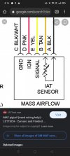
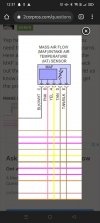
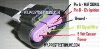
I'm in the process of replacing a MAF sensor plug in my ve commodore and I'm just looking for a wiring diagram with the coloured wires:
Yellow, Black, Red, Pink and Red/White. The plug I'm using is GM brand for a ve commodore and the actual sensor housing is Bosch. The plug I'm using is the one pictured and I've found these two wiring diagrams but was just wanting them put into what coloured wires go where for me.
Thanks
Maddison
Yellow, Black, Red, Pink and Red/White. The plug I'm using is GM brand for a ve commodore and the actual sensor housing is Bosch. The plug I'm using is the one pictured and I've found these two wiring diagrams but was just wanting them put into what coloured wires go where for me.
Thanks
Maddison