Welcome to Just Commodores, a site specifically designed for all people who share the same passion as yourself.

New Posts Contact us

Just Commodores Forum Community

It takes just a moment to join our fantastic community

Register

Help rewiring AC to Haltech

Draimond

Well-Known Member
Joined
Aug 28, 2008
Messages
285
Reaction score
260
Points
63
Location
Brisbane
Members Ride
VS V6 Executive
This being just one of the million things I'm having to tick off during my V6's turbo haltech conversion, I really feel like my brain is resisting engagement on this particular part. I'd rather be fabricating or polishing alloy than wiring up my AC. So to help with said struggles, I'm going to lay it all down here and try and come up with a solution. I also have no idea what I'm doing yet so any input, ideas and help would be appreciated.

My initial zero thought assumption was I just needed two wires from the ECU to control the AC.

I then checked the relay in the engine bay and it appears that there's 3 wires that run to the factory PCM loom.

The AC switch on the dash has five wires which appear to head towards the BCM or they pass through the firewall with the BCM wiring cluster.

Haltech uses up to 4 inputs/outputs.
  • Request - (like your on/off switch) AVI +5V
  • Output - DPO to engage the compressor
  • Pressure sensor - AVI +5V
  • Temp Sensor - AVI +5V
Haltech config allows high rpm compressor shut off, idle target increase and thermo fan control.

Random thought, considering haltech is made to run in a 12 volt car, there is a frustrating amount of 5V

The first glaring problem I see is that the Haltech's AVI on-off switch is looking for 5 volts...

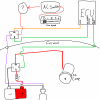
Anyway, so I still need two wires from the ECU into the engine bay headed over to the VS engine bay relay box. Which will be the compressor trigger and the pressure switch...

Screenshot_20240316-041925_1.png


That's the 3 wires that head up the BCM loom from the engine bay relay box and break out to the PCM loom just before the firewall in the engine bay.
 
Last edited:

shane_3800

Well-Known Member
Joined
Aug 13, 2011
Messages
4,223
Reaction score
1,798
Points
113
Age
35
Location
places
Members Ride
vr commo
You should only need to ground number two and it will kick in the A/C, then in the haltech when that DPO output is activated set the idle 150-200 higher in the ECU software.
 

Draimond

Well-Known Member
Joined
Aug 28, 2008
Messages
285
Reaction score
260
Points
63
Location
Brisbane
Members Ride
VS V6 Executive
You should only need to ground number two and it will kick in the A/C, then in the haltech when that DPO output is activated set the idle 150-200 higher in the ECU software.

So number one would have to be the DPO then... But that circuit runs all the way through the dash if that wiring diagram is correct, which I don't actually think it is or rather is such an over simplification that it misrepresents the actual wiring.

And if there is a thermostat switch the circuit won't complete because I don't have one that I'm aware of.

And that still doesn't address needing 5 volt input to let the Haltech know that the AC is requested.
 

Draimond

Well-Known Member
Joined
Aug 28, 2008
Messages
285
Reaction score
260
Points
63
Location
Brisbane
Members Ride
VS V6 Executive
Ok never mind..
So wire 2 can be run as the DPO with it's active state to low / ground.

Wire 1 can go to ignition switched positive I think...
 

Draimond

Well-Known Member
Joined
Aug 28, 2008
Messages
285
Reaction score
260
Points
63
Location
Brisbane
Members Ride
VS V6 Executive
I was thinking something like this but I've just realised I've got the polarity back to front for the fan speed and AC switch.

That's using a high state DPO configuration.

I guess a low state could be less work maybe, but I'm not convinced without having a bit of a deep dive
 

Attachments

  • Untitled2_20240316081007.png
    Untitled2_20240316081007.png
    320.8 KB · Views: 38

Draimond

Well-Known Member
Joined
Aug 28, 2008
Messages
285
Reaction score
260
Points
63
Location
Brisbane
Members Ride
VS V6 Executive
Yeah no that's circuits not going to work at all.

I'd really like to get the pressure switch on the input side so the ECU knows that the AC compressor is getting disengaged.
 

shane_3800

Well-Known Member
Joined
Aug 13, 2011
Messages
4,223
Reaction score
1,798
Points
113
Age
35
Location
places
Members Ride
vr commo
I think wire 1 is just a sense wire so the module in the OE setup can see if there is ground or no ground there.
I may be wrong, but all you need is to energise the relay and the clutch will engage.
 

Draimond

Well-Known Member
Joined
Aug 28, 2008
Messages
285
Reaction score
260
Points
63
Location
Brisbane
Members Ride
VS V6 Executive
Yeah no you're probably right... although the ground goes to the PCM. It would have to be a dedicated ground switch for the AC, surely, it could use that as a sense as well.

That would mean the clutch gets power from the fuse block under the steering wheel. That would explain the chunky terminals on the AC switch. It's probably got 10 amps running through it.

So:

Wire 1 goes to the positive side of a relay's switch at the Haltech which grabs 5 volt from the 5 volt supply and sends that to the AVI AC switch input.
Which keeps the pressure switch on the input side too.

Wire 2 is DPO AC output set to active state ground.

Wire 3 goes to the engine loom to activate the AC clutch.

Bloody hell, that's starting to sound sorted. Thanks Shane!
 

shane_3800

Well-Known Member
Joined
Aug 13, 2011
Messages
4,223
Reaction score
1,798
Points
113
Age
35
Location
places
Members Ride
vr commo
Wire 1 will get full 12vdc.
It likely has a current/voltage shunt in the OE module.
So you would only want to use the DPO as that should be 12vdc.
 

shane_3800

Well-Known Member
Joined
Aug 13, 2011
Messages
4,223
Reaction score
1,798
Points
113
Age
35
Location
places
Members Ride
vr commo
I think the 5v lines would be for a PWM A/C compressor for swash plate control.
 
Top