nick88
New Member
- Joined
- Jul 4, 2005
- Messages
- 368
- Reaction score
- 0
- Points
- 0
- Age
- 35
- Location
- Vic
- Members Ride
- VE2 SS Voodoo
Hey guys, this is my first How To so plz be kind
Ok, well to start with i wanted to wire up some relays so i can have the radio stay on until i open the drivers door with the key off, exactly like the VZ Commodores, so i did a bit of internet searching and came across the site, http://www.the12volt.com (i think he used to be a member on these forums?) and found exactly what i was looking for, but at first it didnt work and with alot of head scratching and different wiring setups i realised i had the wrong relays! lol, so got the right ones and sure enough it worked:yeah:... ok so here goes the How To:
What you will need:
Wire Stripper/Crimper
Electrical Wire - dont need heaps but couple of meters to be safe and maybe some different colours to so you know what wires what
Box of Female blade terminal connectors (6.3mm Tab)
In-Line fuse Holder + fuse
Electrical Tape
2x SPDT relays can get them at autobarn but make sure they are 5-pin with an 87 and 87a terminals (Relays, Single Pole Double Throw (SPDT), Automotive Relays)
Steps:
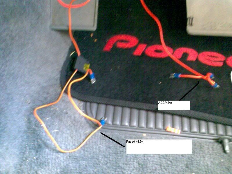
1.First off this was done on a VS so if you have a different model find out what your wiring colours are first, now we need to tap into the Acc wire and a constant +12v wire, i did this at the back of my Headunit. The Acc wire is the Yellow wire and the constant 12V is the Orange/White wire, splice into these with some extra wire(enough to get over to the fuse panel area) and remember which wire is what.
2. Now we need to get a wire from the drivers door swtich to the fuse panel area, Pull off the kick panel on that side then undo the screw holding the door switch in and pull it out now feed another wire through that hole and into the area where the kick panel went, there are a couple of openings you can use, make sure that you have enough wire there to get it from the switch to the fuse panel area, now with the end that does to the door switch you need to splice it into one of the connectors there, i did this by cutting off the original one there, twisting the two wires together and crimping a new female blade terminal onto it, then just put that all back how it came out and remember which wire you just did, at this stage to we need to make a constant ground wire, i just got a piece of wire and put a ring terminal on one end and blade terminal on the other and secured that ring onto the screw that holds the fuse panel thing with all the fuses in place.
3. Now with the constant +12v wire, you need to wire in a in-line fuse, pretty simple to do, just hook one end of the in-line fuse to the +12v and keep the other end bare for now....ok so now we have most of the wires we want, this pic is of how we need to wire the relays in:
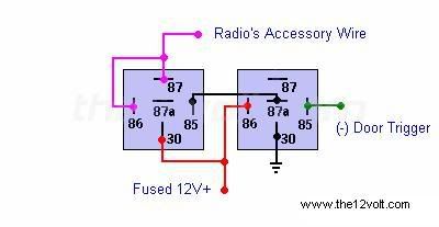
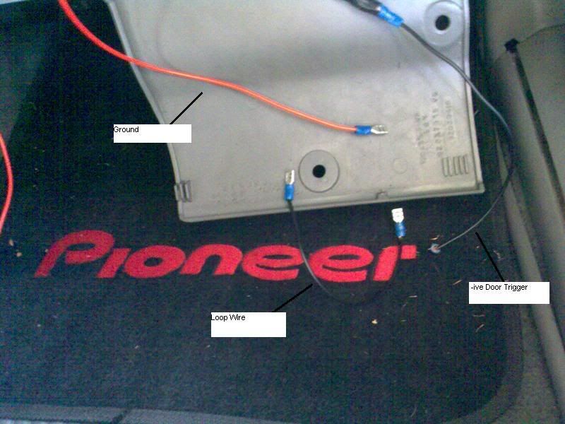
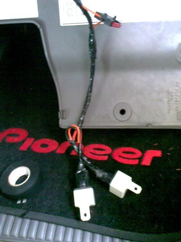
So as you can see we need to make two terminal connections for the Acc wire and +12v wire, thats as simple aas crimping the main wire with a secondary wire in to together and then crimp another terminal to the end of the 2nd wire, and also we need to make a loop wire, simple as cut a short length of wire and crimp a blade terminal onto either end
4. this is what you should have so far
5. ok now we just need to wire in the relays which is as simple as following the above diag, on Relay 1 connect the Acc wire to terminals 86 and 87 one of the +12v wires to pin 30 and one end of the loop wire to pin 85, Relay 2 connect other end of the loop wire to 87a, other +12v to pin 86, the constant ground to pin 30 and the door trigger to pin 85
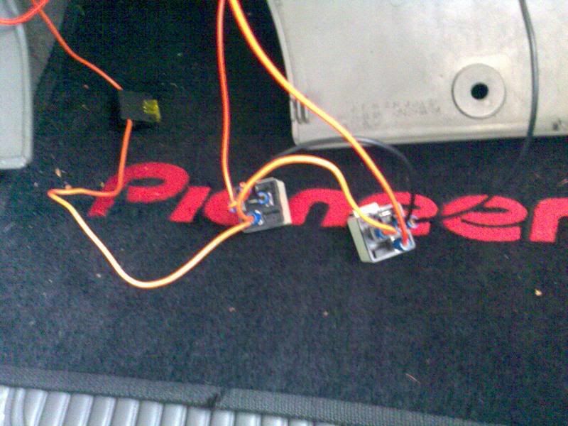
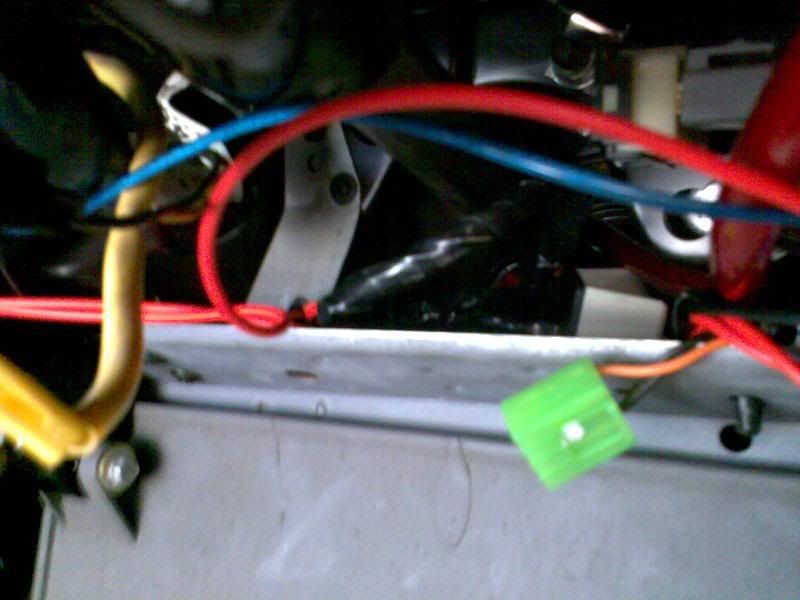
This is what it should look like
6. A this stage put a 7.5/10 amp fuse in the in-line fuse holder and test the circuit out to make sure it works...hopefully it does
Once you've made sure all is good and works tape up the wires and stuff to make it look neat and to stop the possibility of any shorting out.
7. Then replace any parts you have taken off and place the relay's/wiring up inside the fuse panel area, i put mine here.
8. Now clean up and admire your work!...lol:w00t:
Hope this covers everything needed to do this, if not and i remember anything ill add it here or if you feel ive left something out please let me know.
Nick
Ok, well to start with i wanted to wire up some relays so i can have the radio stay on until i open the drivers door with the key off, exactly like the VZ Commodores, so i did a bit of internet searching and came across the site, http://www.the12volt.com (i think he used to be a member on these forums?) and found exactly what i was looking for, but at first it didnt work and with alot of head scratching and different wiring setups i realised i had the wrong relays! lol, so got the right ones and sure enough it worked:yeah:... ok so here goes the How To:
What you will need:
Wire Stripper/Crimper
Electrical Wire - dont need heaps but couple of meters to be safe and maybe some different colours to so you know what wires what
Box of Female blade terminal connectors (6.3mm Tab)
In-Line fuse Holder + fuse
Electrical Tape
2x SPDT relays can get them at autobarn but make sure they are 5-pin with an 87 and 87a terminals (Relays, Single Pole Double Throw (SPDT), Automotive Relays)
Steps:
1.First off this was done on a VS so if you have a different model find out what your wiring colours are first, now we need to tap into the Acc wire and a constant +12v wire, i did this at the back of my Headunit. The Acc wire is the Yellow wire and the constant 12V is the Orange/White wire, splice into these with some extra wire(enough to get over to the fuse panel area) and remember which wire is what.
2. Now we need to get a wire from the drivers door swtich to the fuse panel area, Pull off the kick panel on that side then undo the screw holding the door switch in and pull it out now feed another wire through that hole and into the area where the kick panel went, there are a couple of openings you can use, make sure that you have enough wire there to get it from the switch to the fuse panel area, now with the end that does to the door switch you need to splice it into one of the connectors there, i did this by cutting off the original one there, twisting the two wires together and crimping a new female blade terminal onto it, then just put that all back how it came out and remember which wire you just did, at this stage to we need to make a constant ground wire, i just got a piece of wire and put a ring terminal on one end and blade terminal on the other and secured that ring onto the screw that holds the fuse panel thing with all the fuses in place.
3. Now with the constant +12v wire, you need to wire in a in-line fuse, pretty simple to do, just hook one end of the in-line fuse to the +12v and keep the other end bare for now....ok so now we have most of the wires we want, this pic is of how we need to wire the relays in:
So as you can see we need to make two terminal connections for the Acc wire and +12v wire, thats as simple aas crimping the main wire with a secondary wire in to together and then crimp another terminal to the end of the 2nd wire, and also we need to make a loop wire, simple as cut a short length of wire and crimp a blade terminal onto either end
4. this is what you should have so far
5. ok now we just need to wire in the relays which is as simple as following the above diag, on Relay 1 connect the Acc wire to terminals 86 and 87 one of the +12v wires to pin 30 and one end of the loop wire to pin 85, Relay 2 connect other end of the loop wire to 87a, other +12v to pin 86, the constant ground to pin 30 and the door trigger to pin 85
This is what it should look like
6. A this stage put a 7.5/10 amp fuse in the in-line fuse holder and test the circuit out to make sure it works...hopefully it does
Once you've made sure all is good and works tape up the wires and stuff to make it look neat and to stop the possibility of any shorting out.
7. Then replace any parts you have taken off and place the relay's/wiring up inside the fuse panel area, i put mine here.
8. Now clean up and admire your work!...lol:w00t:
Hope this covers everything needed to do this, if not and i remember anything ill add it here or if you feel ive left something out please let me know.
Nick
