Welcome to Just Commodores, a site specifically designed for all people who share the same passion as yourself.
You are using an out of date browser. It may not display this or other websites correctly.
You should upgrade or use an alternative browser.
You should upgrade or use an alternative browser.
[Ecotec] Cam Crank Voltage
- Thread starter Draimond
- Start date
Draimond
Well-Known Member
- Joined
- Aug 28, 2008
- Messages
- 285
- Reaction score
- 260
- Points
- 63
- Location
- Brisbane
- Members Ride
- VS V6 Executive
Just spoke to Haltech and the bloke I spoke to said that's exactly how the sensors work, they take a 12V input and output a 0-5V signal for the ECU.
Power from the fuse box in the engine bay can be unshielded, signal and signal ground wires should be shielded.
I still don't understand why a signal ground wire needs to be shielded when its shield gets spliced into the signal grounds at the ECU anyway.
I need aspirin...
Power from the fuse box in the engine bay can be unshielded, signal and signal ground wires should be shielded.
I still don't understand why a signal ground wire needs to be shielded when its shield gets spliced into the signal grounds at the ECU anyway.
I need aspirin...
Draimond
Well-Known Member
- Joined
- Aug 28, 2008
- Messages
- 285
- Reaction score
- 260
- Points
- 63
- Location
- Brisbane
- Members Ride
- VS V6 Executive
Would anybody be able to test the cam or crank sensor for me on their car?
Should be ground, power and 0 to 5 volt on the cam. Ground, power plus two sets of 0 to 5 volt on the crank.
I would assume you can test the by turning the ignition on and unplugging one of the sensors, then probing the connectors pins with a voltmeter.
The cam and crank sensors voltage input is shared, the same wire is spliced into a single output on the DFI module. So test whichever is easiest to get to for you.
Basically I just need to know if you're getting ground, 12 volt and 5 volt or ground and a bunch of 5 volt.
I think the only thing I can do at home would be to throw the DFI module on the bench with a battery and see if I can get it powered up out of the car as I've already chopped up my wiring harness and fuse box.
07GTS
Well-Known Member
- Joined
- Sep 8, 2013
- Messages
- 5,002
- Reaction score
- 6,680
- Points
- 113
- Location
- Australia
- Members Ride
- VEGTS BUILT BLOWN E85
top diagram here may help its VS - VY
 premierautotrade.com.au
Testing CAM Angle Sensors (CAM)
What Technicians need to know about on car testing of CAM angle position sensors and related circuitry.
07GTS
Well-Known Member
- Joined
- Sep 8, 2013
- Messages
- 5,002
- Reaction score
- 6,680
- Points
- 113
- Location
- Australia
- Members Ride
- VEGTS BUILT BLOWN E85
yea sounds like the battery 12-14v supply for it, is the reference wire 5v when sensor disconnected ? most of the time that can be a 5v from ecu and the sensor just needs power/earth and then it just pulls that 5v down to zero when it passes teeth
- Joined
- Apr 15, 2006
- Messages
- 22,638
- Reaction score
- 20,532
- Points
- 113
- Location
- Sth Auck, NZ
- Members Ride
- HSV VS Senator, VX Calais II L67
I think it's 12 volt in as the supply but the signal is 0-5volt out.
Draimond
Well-Known Member
- Joined
- Aug 28, 2008
- Messages
- 285
- Reaction score
- 260
- Points
- 63
- Location
- Brisbane
- Members Ride
- VS V6 Executive
I don't think it's 5v disconnected. I believe the sensors has a resistor that pulls the 12 volt down to 5....yea sounds like the battery 12-14v supply for it, is the reference wire 5v when sensor disconnected ? most of the time that can be a 5v from ecu and the sensor just needs power/earth and then it just pulls that 5v down to zero when it passes teeth
I'm going to run with Haltech's advice that it takes 12 volt in. It's going to be a massive job if it's wrong, because my 12 volt is in the engine bay and my 5 volt supply is from the ECU and they need to be shielded wires.
- Joined
- Apr 15, 2006
- Messages
- 22,638
- Reaction score
- 20,532
- Points
- 113
- Location
- Sth Auck, NZ
- Members Ride
- HSV VS Senator, VX Calais II L67
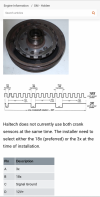
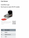
The CAS is a hall effect sensor x2