DIY: Changing the clockspring - Step-by-step
So here is my step by step tutorial on how to change the clock spring on a VT. Please be patient as this is the first time ive posted such a thing on the forum. I hope it helps anyone out there. It is quite a simple job and doesn't require much technical skill.
The clock spring operates the horn and airbag, and in somecases a 3-wire CS will operate the radio steering wheel controls. The reason im changing mine is because my SRS warning light turned on. If you read my posts above im trying to solve this problem.
Note: im not sure if it has fixed my problem just yet - because SRS error codes require a scan tool to be cleared, so i wont know until then. When i do i'll let people know if it fully worked or not.
Tools Needed:
16mm socket
T30H Torx socket
Torque wrench (optional)
Steering wheel puller (optional)
First things first. SAFETY. I am no expert on airbag safety but the first thing you should do is go and unplug the negative terminal (i do both for good measures it's not going to hurt). Wait atleast 2 minutes. Another precaution my old man taught me is to press the brakes just to drain any extra juice stored in capacitors and what not.
And as always, when playing with an airbag, dont go hitting it or dropping it and keep it faced away from you and store it face-up. I also unplugged the airbag fuse.
Also align your steering wheel and wheels to the straight ahead position
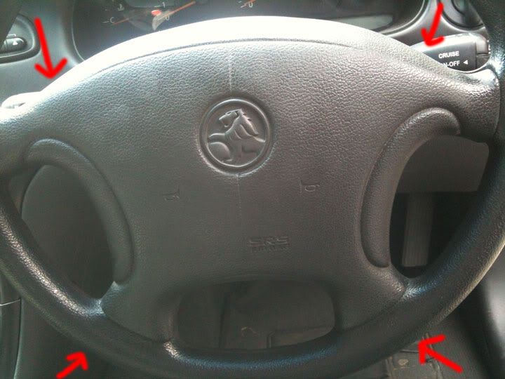
Behind the airbag horn pad are for 4 x T30H Torx screws. Take these out, and when you're upto the last one make sure the pad doesn't suddenly fall and yank on CS wires behind. (Even though we are changing it).
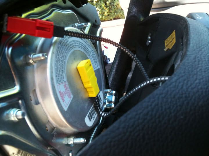
Peek in behind the horn pad and you will notice the clips attatched.
The red horn wire needs a small tipped screw driver to push in a tab and then wiggle off.
As for the yellow airbag clip, as to not force the clip off and break anything delicate I found that 2 screw drivers on either sides of the clip is the best way to evenly pop it out.
Once this is done, place the horn pad and airbag assembly somewhere safe face up.
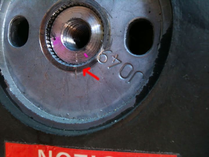
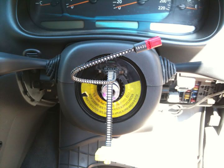
You should now be able to see the main steering wheel retaining bolt.
Using a 16mm socket, this weirdly shaped nut should come off easily. Dont go pulling off the wheel just yet.
Next get a scriber/screw driver/marker and mark the position of the steering wheel to the shaft on the edges so that you can put it back on straight after
Ok before you go pulling off the wheel, put the steering wheel bolt back on a few threads, so this way when you pull off the wheel it doesn't suddenly jerk off smacking you in the face or wrecking any clockspring wires (even though we are changing it).
Using a bit of force pull the wheel off. Now undo the bolt, and feed the clockspring wires through the gap in the steering wheel.
You should now be faced with the clumsy column clovers.
Remove the top cover by positioning the column fully down. Either way its going to need some fidgeting but slide the top cover towards the driver and up.
Keep in mind that the rubbers on the indicators give the job a bit of resistance.
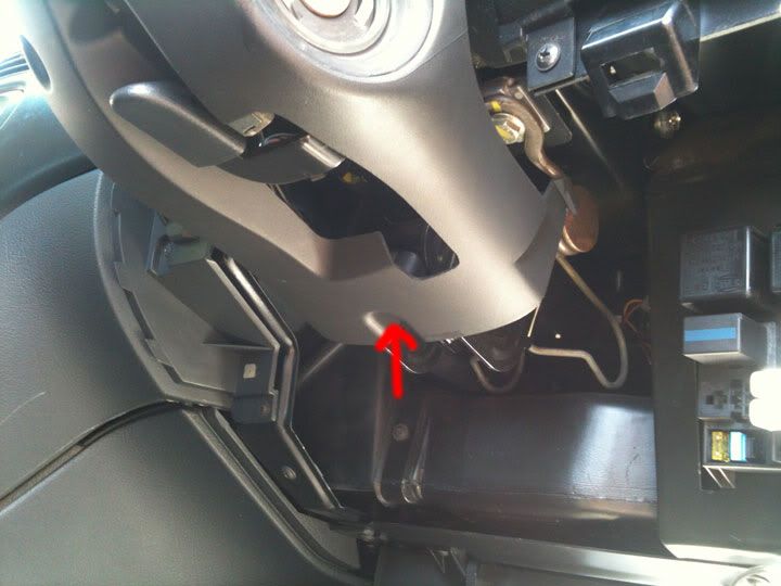
Next we remove the bottom cover. Position the column fully up. It also helps if you drop the fuse cover below the column so its out of the way.
Undo the screw highlighted in the picture below. Also the lock cylinder rubber and the indicator rubbers are going to make it a little fidgetty aswell.
Slide the bottom cover towards the driver and then down.
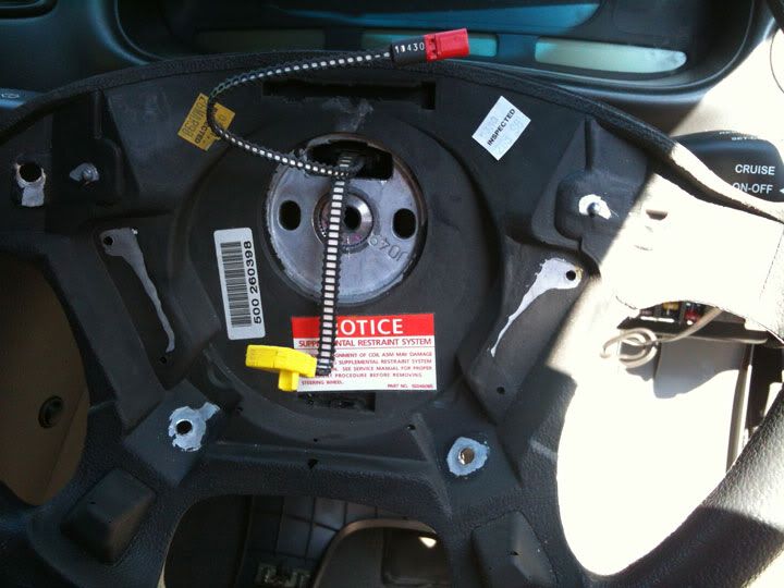
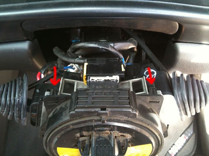
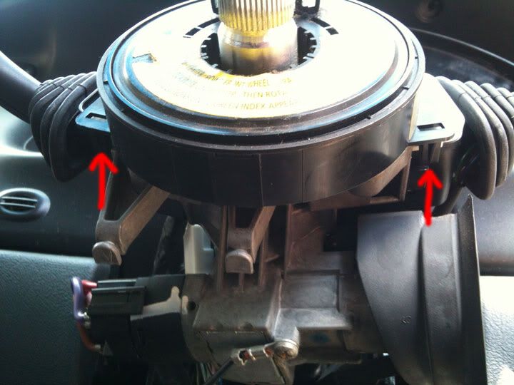
The clock spring is held to the column by 4 clips. They are pretty obvious but i've added some pictures anyhow
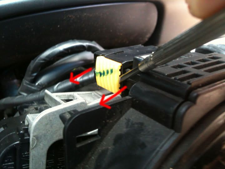
The clock spring has a wiring harness attatched. The way to unplug this is to get a screwdriver and wedge the yellow clipwedge outwards.
Take off the clock spring and your done.
When I was at the wreckers the guy checked the clock spring's continuity for me, and also said something about it needs to be 0.4ohms (I'm not sure of this).
He also said the yellow square clip on the CS has a resistor in it and can't be checked for continuity directly. (Im not sure on this either)
I noticed myself that there were little numbers on each connector. Possibly the ohmage/resistance they should be? Anyhow, i got continuity through the horn and none for the airbag wire.
To measure this your going to need a multimetre and a thin wire to jam into the clips.
Looking at the clock springs contacts. From the left, #1 - #2 are the airbags, and #3 - #4 are the horns.
Before putting the new clock spring on its best to centre it so as not to break it.
There are instructions on a sticker on the CS on how to do this.
However if not, hold the outer hub with one hand. Spin the inner hub in clockwise until it stops (Dont use any force).
Now rotate the inner hub 2.5 turns in the opposite direction until the green tab can be seen in the little window.
The installation is the reversal of above, but pay attention to:
Aligning the steering wheel and the steering shaft to the marks you put.
Tighten the steering wheel retaining nut to 40-50Nm.
Tighten the airbag assembly torx screws to 10-14Nm.
Remember to plug the battery and fuse back in before turning on the ignition.
As a safety precaution turn the ignition on standing out of the car just incase.
All done, i hoped this has helped someone.
I will post back on here after the scan tool reset if the clock spring really was the problem for my SRS light coming on.
Update: Good news for me, I just got back from the auto elec after having the code cleared and my SRS light hasn't turned on or beeped.
")