Welcome to Just Commodores, a site specifically designed for all people who share the same passion as yourself.

New Posts Contact us

Just Commodores Forum Community

It takes just a moment to join our fantastic community

Register

123esproc

Member
Joined
Mar 18, 2017
Messages
68
Reaction score
6
Points
8
Age
37
Location
South australia
Members Ride
Vx ss vs ss
Ok cheers heaps ….3 or a 4 wire what ? Plug?
My mate just tried connecting his scan tool to the obd port and there’s no connection… just like when I tried to bridge the pins 5&6
 

123esproc

Member
Joined
Mar 18, 2017
Messages
68
Reaction score
6
Points
8
Age
37
Location
South australia
Members Ride
Vx ss vs ss
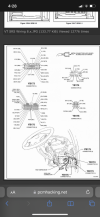
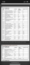
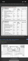
I can’t seem to open the file but I found another one online
But unsure which ones I should be testing
 

Attachments

  • 5576F9AE-1D59-4269-B877-68C4ACC1879E.png
    5576F9AE-1D59-4269-B877-68C4ACC1879E.png
    450.3 KB · Views: 93
  • 06F1EBBA-4542-4F7F-94FF-1C2382E98111.png
    06F1EBBA-4542-4F7F-94FF-1C2382E98111.png
    538.1 KB · Views: 112
  • 9CD05C5F-42D7-4DB5-B098-346D253EE442.png
    9CD05C5F-42D7-4DB5-B098-346D253EE442.png
    506.9 KB · Views: 99

Jolls

Donating Member
Joined
Mar 2, 2017
Messages
941
Reaction score
1,622
Points
93
Location
Murrumbateman
Members Ride
VY SS Ute (Jimi Hendrix)
You need to download it and then open it using a decent pdf reader like Adobe or Foxit
 

123esproc

Member
Joined
Mar 18, 2017
Messages
68
Reaction score
6
Points
8
Age
37
Location
South australia
Members Ride
Vx ss vs ss
Yeah it’s not working properly
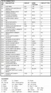
I’ve uploaded the ones I found
 

Attachments

  • EB2E2EBF-F5A4-4659-A7ED-67331CD6C4F3.jpeg
    EB2E2EBF-F5A4-4659-A7ED-67331CD6C4F3.jpeg
    153 KB · Views: 97

Jolls

Donating Member
Joined
Mar 2, 2017
Messages
941
Reaction score
1,622
Points
93
Location
Murrumbateman
Members Ride
VY SS Ute (Jimi Hendrix)
Comms between the modules and the transfer of signals is done using the serial interface bus. Signal to the fuel pump relay is drect from the PCM to the relay itself. The wire from the PCM to the relay should be green/white trace as shown below.

1668417458267.png
That should be pin 8 on connector YE 123 as shown below.

1668417962794.png


If you can get the fuel pump to run bridging the relay your problem is now working out why the signal is not being sent by the PCM.

I trust this helps.

Cheers n Beers
Jolls
 
Last edited:

Jolls

Donating Member
Joined
Mar 2, 2017
Messages
941
Reaction score
1,622
Points
93
Location
Murrumbateman
Members Ride
VY SS Ute (Jimi Hendrix)
You need to read the codes to understand what is telling the PCM not to send the signal to the relay.

What scanner was your mate using?
 

123esproc

Member
Joined
Mar 18, 2017
Messages
68
Reaction score
6
Points
8
Age
37
Location
South australia
Members Ride
Vx ss vs ss
THERE IS NO CODES BECAUSE NO SCANNER WILL CONNECT! I don’t know how many more times I need to say this I’ve tried 3 scanners and a paper clip …nothing
Maybe the issue is coming from the wiring to the obd….. that’s why I’ve mentioned about it NOT working

Thanks heaps for the info and pic I really appreciate the help… I assume I’m looking for 12v on pin 8 when key is triggered?
 

Jolls

Donating Member
Joined
Mar 2, 2017
Messages
941
Reaction score
1,622
Points
93
Location
Murrumbateman
Members Ride
VY SS Ute (Jimi Hendrix)
That's the way I read it but I haven't dug right into the detail. I expect when the key is turned the PCM should pull in the fuel pump relay and pressurise the fuel rail. To do this though it has to receive a message from the BCM. Note that the key turning only energises the relay - it doesn't send any signal to pull it in.

If the scanner can't read there is a problem with the connection to the BCM as it is really just an extension of the BCM pin inputs and outputs. This needs to be your first fault finding step. Until you can communicate with the BCM and through it the other modules it is not likely that you will get an OK to start signal from the PCM.

So why don't the scanners work. Do they power up? If not check that there is a constant 12V+ at pin 16 of the Data Link Connector (DLC pr obd port as you are calling it). There should also be 12V+ when the ignition is turned on at Pin 6 to feed the PIM and earth at pins 4 and 5. I recommend that you start there and work your way through it. then start checking the serial data connections for continuity, Once you have proofed the circuit then it is time to work out what the next step is.

1668489440276.png


To solve this you are going to need the manual. I trust this helps you.

Cheers n Beers
Jolls
 

123esproc

Member
Joined
Mar 18, 2017
Messages
68
Reaction score
6
Points
8
Age
37
Location
South australia
Members Ride
Vx ss vs ss
Ok so firstly thank you very much for the info…. There is only 1.6 bolts at pin 16 and zero bolts at pin 6
And yea the code readers would not power up
 

Jolls

Donating Member
Joined
Mar 2, 2017
Messages
941
Reaction score
1,622
Points
93
Location
Murrumbateman
Members Ride
VY SS Ute (Jimi Hendrix)
So for mine there are two things to look at now and they are probably both related. Check voltage on both sides of the fusible link and fuse 31 and check continuity to pin 16 and the BCM. Then with the ignition on do the same to F14 and the BCM. There is definitely an issue to be resolved in relation to power from the battery to the DLC and BCM.

Once that has been solved time to move the next step.

Cheers n Beers
Jolls
 
Top